Electrical Connections
Electrical Connections
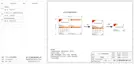
Grid Cable and Micro-breaker recommended
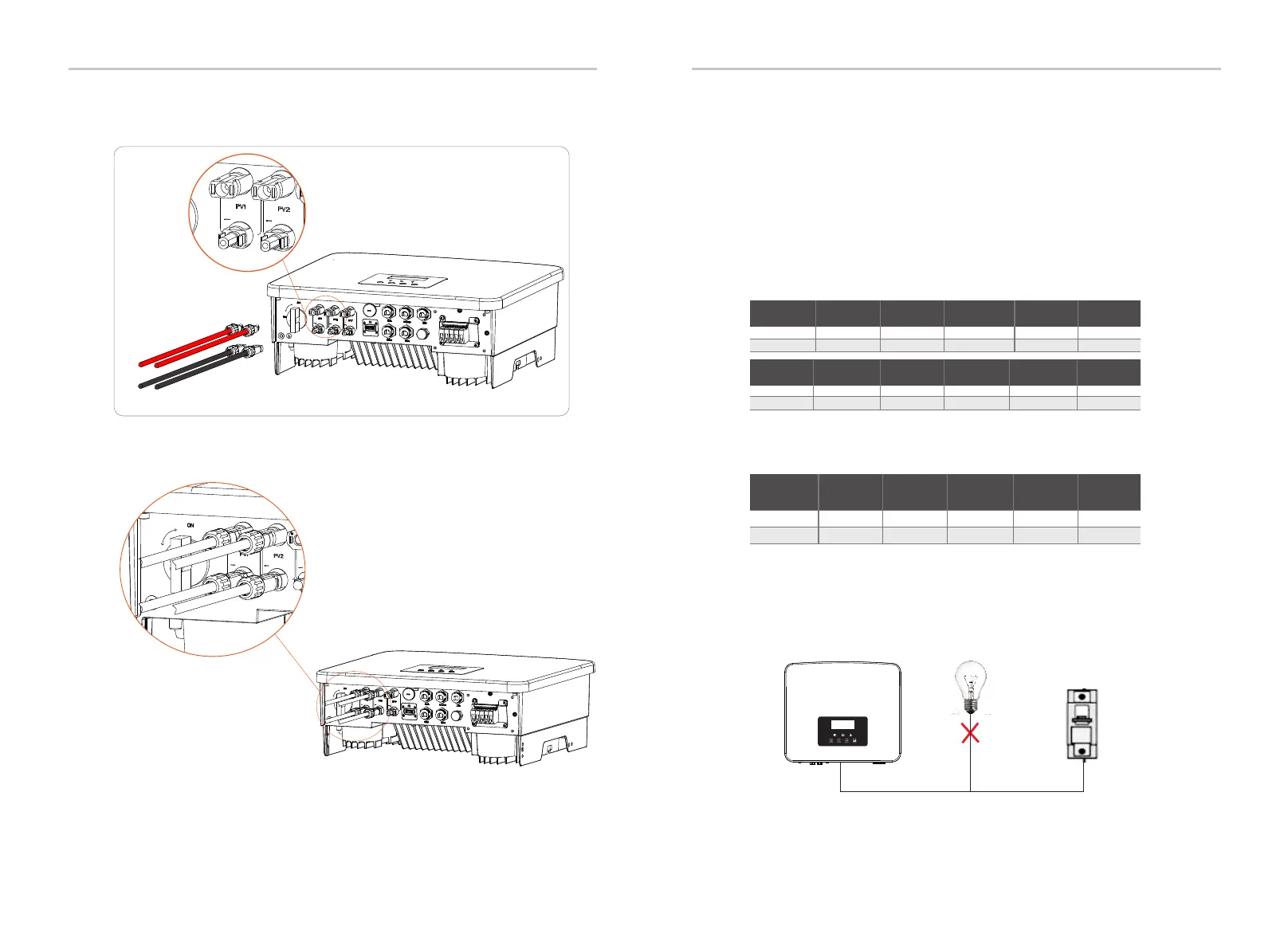
Figure: Wrong connection of load and inverter
Ø Grid port connection
EPS(Off-grid) Cable and Micro-breaker recommended
6.2 Grid Port and EPS(Off-grid) Output Connection
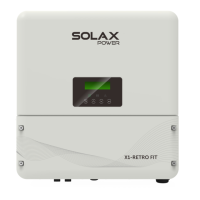
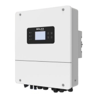
Schematic diagram of the inverter PV connected.
38
39
D
ongle/
U
pgr
ad
e
The series inverter are single-phase inverter. Suitable for rated voltage
220/230/240 V, frequency 50/60 Hz. For more technical requirements,
please consult the requirements of the local public grid.
The circuit breaker should be installed between the inverter and the
mains, and the load should not be directly connected to the inverter.
The following is the location of the inverter positive and negative
(PV+/PV-) ports.
PV1+
PV2+
PV1-
PV2-
Don
gl
e/U
p
g
r
a
de
Cable (copper)
Micro-Breaker
Model
X1-Hybrid-7.5-D
50 A
8-10 mm²
X1-Hybrid-6.0-D
8-10 mm²
50 A
X1-Hybrid-3.7-D
6-8 mm²
40 A
X1-Hybrid-3.0-D
4-6 mm²
32 A
Cable (copper)
Micro-Breaker
X1-Hybrid-3.0-M
3-4 mm²
25 A
X1-Hybrid-3.7-M
3-4 mm²
25 A
X1-Hybrid-6.0-M
4-6 mm²
32 A
X1-Hybrid-7.5-M
4-6 mm²
32 A
Model
X1-Hybrid-5.0-M
4-6 mm²
32 A
X1-Hybrid-5.0-D
8-10 mm²
50 A
X1-Hybrid-5.0K-D
Cable (copper)
Micro-Breaker
50 A
8-10 mm²8-10 mm²
50 A
6-8 mm²
40 A
4-6 mm²
32 A
Cable (copper)
Micro-Breaker
3-4 mm²
25 A
3-4 mm²
25 A
4-6 mm²
32 A
4-6 mm²
32 A
4-6 mm²
32 A
8-10 mm²
50 A
Cable (copper)
Micro-Breaker
Model
X1-Hybrid-3.0-D
X1-Hybrid-3.0-M
3-4 mm²
25 A
X1-Hybrid-3.7-D
X1-Hybrid-3.7-M
3-4 mm²
25 A
4-6 mm²
X1-Hybrid-6.0-D
X1-Hybrid-6.0-M
32 A
4-6 mm²
X1-Hybrid-7.5-D
X1-Hybrid-7.5-M
32 A
4-6 mm²
X1-Hybrid-5.0-D
X1-Hybrid-5.0-M
32 A
X1-Hybrid-5.0K-D
Model
X1-Hybrid-3.0-D X1-Hybrid-3.7-D X1-Hybrid-6.0-D X1-Hybrid-7.5-D
X1-Hybrid-5.0-D
X1-Hybrid-5.0K-D
Model
X1-Hybrid-3.0-M X1-Hybrid-3.7-M X1-Hybrid-6.0-M X1-Hybrid-7.5-M
X1-Hybrid-5.0-M

 Loading...