3 Introduction
3.1 Basic Features
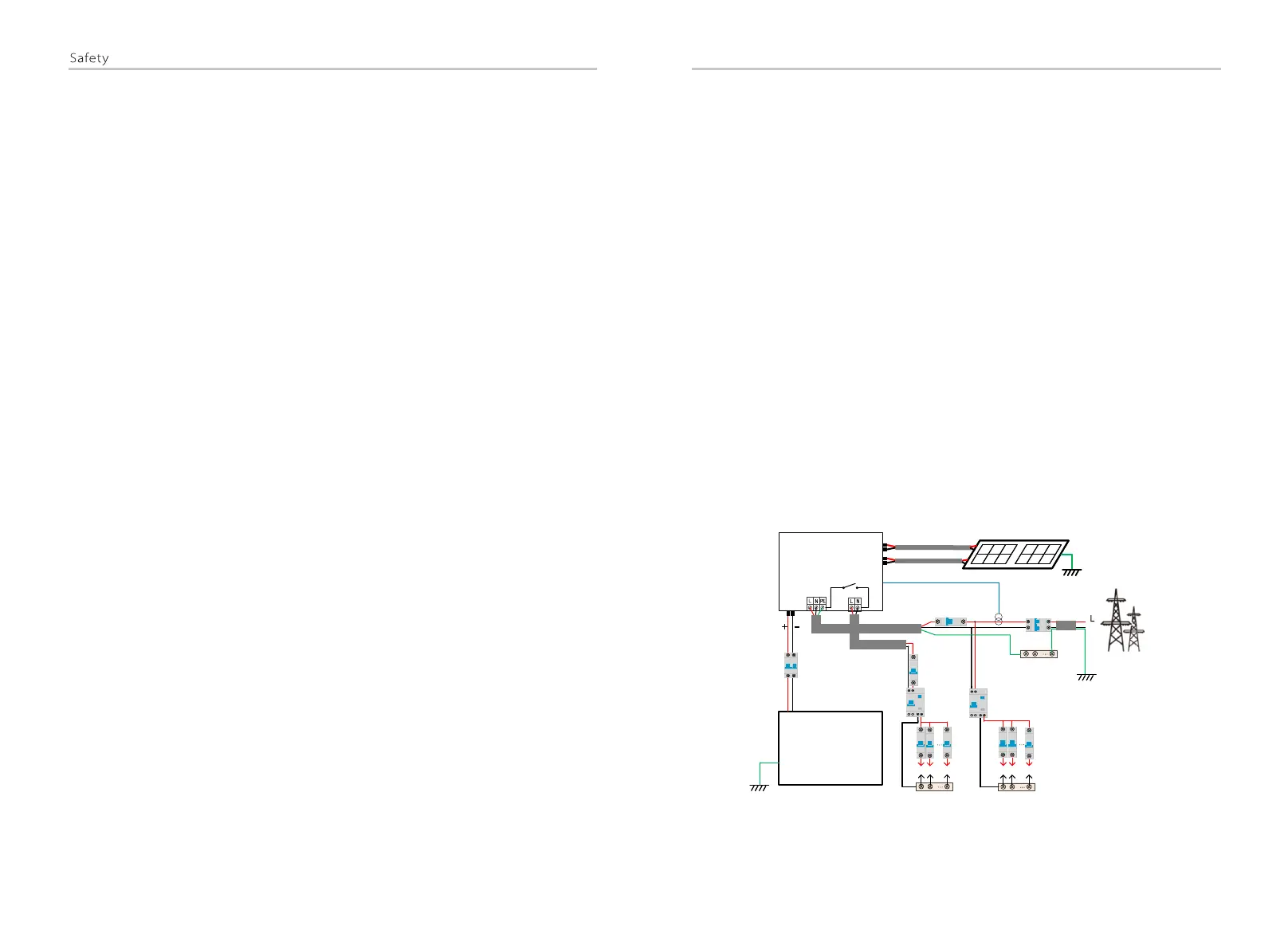
3.2 System Diagram
Introduction
12
13
2.3 EC Directives
The assembly shall be installed in accordance with the statutory wiring
rules. Install and configure the system in accordance with safety rules,
including the use of specified wiring methods. The installation of the
system can only be done by professional assemblers who are familiar with
safety requirements and EMC. The assembler shall ensure that the system
complies with the relevant national laws. The individual subassembly of
the system shall be interconnected by means of the wiring methods
outlined in national/international such as the national electric code
(NFPA) No. 70 or VDE regulation 4105.
This section describes the requirements of the European low voltage
regulations, including safety instructions and system licensing conditions,
the user must comply with these regulations when installing, operating,
and maintaining the inverter, otherwise personal injury or death may
occur, and the inverter will be damaged.
Please read the manual carefully when operating the inverter .If you do
not understand "Danger", "Warning", "Caution" and the description in the
manual, please contact the manufacturer or service agent before installing
and operating the inverter.
Make sure that the whole system complies with the requirements of
EC(2014/35/EU, 2014/30/EU, etc.) before starting the module (i.e. to start
the operation).
Standard of 2014/35/EU (LVD)
EN IEC 62109-1; EN IEC 62109-2
EN 62477-1
Standard of 2014/30/EU (EMC)
EN IEC 61000-6-1; EN IEC 61000-6-2;
EN IEC 61000-6-3; EN IEC 61000-6-4;
EN IEC 61000-3-2; EN 61000-3-3;
EN IEC 61000-3-11; EN 61000-3-12
EN 55011
This inverter is a high-quality inverter that can convert solar energy into
alternating current and store energy into batteries.
The inverter can be used to optimize self-consumption, stored in
batteries for future use or fed into the public grid. The way it works
depends on user preferences. It can provide emergency power during
power outages.
The series inverter are designed to has four EPS(Off-grid) wiring
schemes, customers can choose EPS(Off-grid) compatible parts
Load and EPS(Off-grid) compatible with all load use.
There are different ways of wiring in different countries, one is to
connect N line with PE line, the other is to separate the line from
the PE line wiring, see below;
Diagram A: Neutral line and PE line are separated from each
other, and the common load is connected to the EPS(Off-grid)
port; (For most countries)
N-BAR for EPS(Off-grid) loads
N-BAR for loads
Grid
N
BAT
Battery
EPS(Off-grid) loads
Loads
Inverter
PV 1
PV 2
E-BAR
RCD
Breaker
Breaker
Grid
EPS(Off-grid)
Main Breaker
Breaker
Breaker
CT
CT
Breaker
PE
RCD

 Loading...