5-42
3-3. SYSTEM CONTROL SYSTEM ADJUSTMENT
1. Battery End Adjustment (VC-206 board)
Set the battery end voltage.
If the voltage is incorrect, the life of the battery will shorten. The
image at the battery end will also be rough.
Mode Camera recording
Subject Arbitrary
Measurement Point LCD display of the adjustment remote
Measuring Instrument commander
Adjustment Page D
Adjustment Address 28 to 2C, 37
Note: The lens block and cabinet (R) must be connected. Switch setting
1) AUTO FOCUS OFF
2) LCD screen Closed
3) NIGHT SHOT OFF
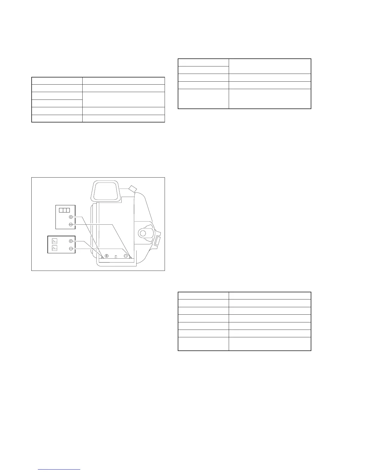
Connection:
1) Connect the regulated power supply and the digital voltmeter
to the battery terminal as shown in Fig. 5-3-4.
Fig. 5-3-4
Adjusting method:
1) Adjust the output voltage of the regulated power supply so that
the digital voltmeter display is 6.1 ± 0.1Vdc.
2) Turn off the power supply.
3) Turn on the HOLD switch of the adjustment remote
commander.
4) Turn on the power supply.
5) Load a cassette, and set to the camera recording mode.
6) Select page: 0, address: 01, and set data: 01.
7) Decrease the output voltage of the regulated power supply so
that the digital voltmeter display is 5.30 ± 0.01Vdc.
8) Select page: 2, address: 51, read the data, and this data is named
Dref.
9) Select page: D, address: 28, set data: Dref, and press the PAUSE
button of the adjustment remote commander.
10) Select page: D, address: 37, set data: Dref, and then press the
PAUSE button of the adjustment remote commander.
11) Convert Dref to decimal notation, and obtain Dref'. (Refer to
“Hexadecimal-decimal conversion table” of “Service mode”)
12) Calculate D29', D2A', D2B' and D2C' using following equations
(decimal calculation), convert it to a hexadecimal number, and
input each adjustment address.
Address: 29 D29' = Dref'+ 11
Address: 2A D2A' = Dref'+ 36
Address: 2B D2B' = Dref'+ 58
Address: 2C D2B' = Dref'+ 66
Note: After setting each data, be sure to press the PAUSE button.
13) Select page: 0, address: 01, and set data: 00.
Digital voltmeter
Regulated power supply
5.30
±
0.01 Vcd
3-4. SERVO SYSTEM ADJUSTMENTS
1. T Reel FG Duty Adjustment (VC-206 Board)
Measurement Point Adjustment remote commander
Measuring Instrument display data
Adjustment Page C
Adjustment Address 59, 6F
Specified Value T reel FG Duty Adjustment:
The data of page: C, address: 6F is
“01”, or “02” , “03”.
Adjusting Method:
1) Set the POWER switch to VTR (or PLAYER).
2) Close the cassette compartment without inserting a cassette.
3) Set the HOLD switch of the Adjustment remote commander to
ON (SERVICE position).
4) Select page: 0, address: 01, and set data: 01.
5) Select page: C, address: 6A, set data: 10, and press the PAUSE
button of the Adjustment remote commander.
6) Select page: 3, address: 09, set data: 00, and press the PAUSE
button.
7) Select page: 3, address: 01, set data: 1A, and press the PAUSE
button. (to start up automatic “T reel FG Duty Adjustments”.)
8) Select page: 3, address: 02, and check that the data is changed
from “17” to “00”.
9) Set the HOLD switch of the Adjustment remote commander to
OFF, and wait more than 2 seconds.
10) Set the HOLD switch to ON.
11) Check that the data of page: 3, address: 04 and that of page: C,
address: 6F are the same.
12) Select page: C, address: 6F. If the data is “01”, or “02”, “03”, it
means that the automatic T reel FG adjustment has ended
normally.
13) Select page: C, address: 6A, set data: 00, and press the PAUSE
button of the Adjustment remote commander.
14) Select page: 0, address: 01, and set data: 00.
15) Turn OFF the power supply.
2. Switching Position Adjustment (VC-206 Board)
Mode VTR Playback
Signal SW/OL reference tape (XH2-3)
Measurement Point Display data of page: 3, address: 03
Measuring Instrument Adjustment remote commander
Adjustment Page C
Adjustment Address 4C, 4D, 4E, 4F
Specified Value The data of page: 3, address: 03 is
“00”.
Adjusting Method:
1) Select page: 0, address: 01, and set data: 01.
2) Select page: 3, address: 01, set data: 0E, and press the PAUSE
button of the Adjustment remote commander.
3) Select page: 3, address: 02, and check that the data is changed
from “0E“ to “00”.
4) Select page: 3, address: 03, and check that the data is “00”.
5) Set the HOLD switch of the Adjustment remote commander to
OFF, and wait more than 2 seconds (so that the adjustment
data is automatically written in page: C, address: 4C to 4F).
6) Set the HOLD switch of the Adjustment remote commander to
ON.
7) Select page: 0, address: 01, and set data: 00.
8) Set to the stop mode.
9) Turn OFF the power supply.
 Loading...