5-53
14. IC9004 EVR Y Adjustment (VI-148 Board)
(Except AEP/UK model)
Set the Y AD OUT level.
Mode VTR stop
Signal 75% color bar (Video signal terminal
of AUDIO/VIDEO jack)
Measurement Point DDS display of LCD or TV monitor
Measuring Instrument (Note 1)
Adjustment Page D
Adjustment Address 9B
Specified Value EA to EC (NTSC)
EA to EC (PAL)
Note 1: The two digits of the display data of the LCD and TV monitor is
the object data.
HI XX XXXX
Object data
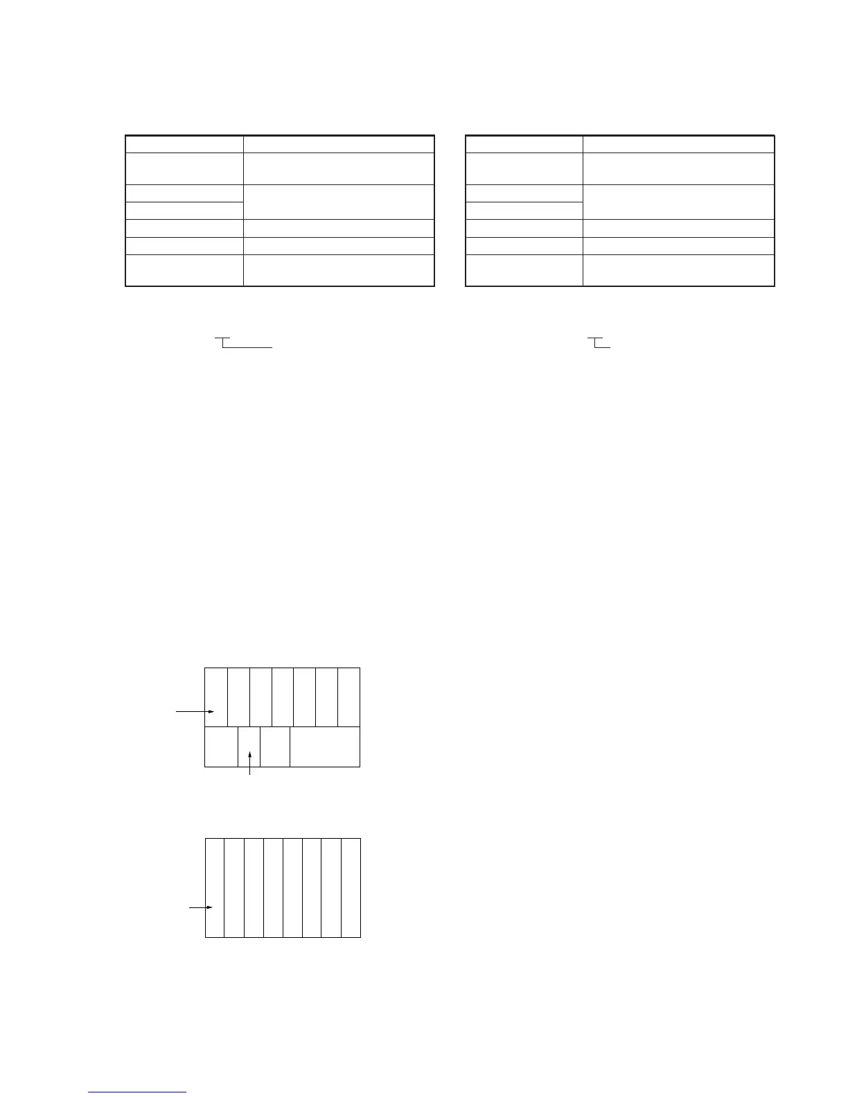
Note 2: Use the 75% color bar signal shown in Fig. 5-3-17.
Adjusting method:
1) Select page: 0, address: 01, and set data: 01.
2) Select page: D, address: 11, set data: 24, and press the PAUSE
button of the adjustment remote commander.
3) Select page: 2, address: 96, and set data: 70 (NTSC) or 40
(PAL).
4) Select page: 2, address: 97, and set data: 50 (NTSC) or 30
(PAL).
5) Select page: D, address: 9B, change the data and adjust the
DDS display data (Note 1) to the specified value.
6) Press the PAUSE button of the adjustment remote commander.
Processing after Completing Adjustments:
1) Select page: D, address: 11, set data: 00, and press the PAUSE
button of the adjustment remote commander.
2) Select page: 0, address: 01, and set data: 00.
3) Select page: 2, address: 96, and set data: 00.
4) Select page: 2, address: 97, and set data: 00.
For NTSC model
For PAL model
Fig. 5-3-17
(75%)
White
Yellow
Cyan
Green
Magenta
Red
Blue
Q
I
White
(100%)
Black
(100%)
Yellow
Cyan
Green
Magenta
Red
Blue
White
Black
15. IC9004 EVR CR Adjustment (VI-148 Board)
(Except AEP/UK model)
Set the CR AD OUT level.
Mode VTR stop
Signal 75% color bar (Video signal terminal
of AUDIO/VIDEO jack)
Measurement Point DDS display of LCD or TV monitor
Measuring Instrument (Note 1)
Adjustment Page D
Adjustment Address 9C
Specified Value 4D to 4F (NTSC)
53 to 55 (PAL)
Note 1: The two digits of the display data of the LCD and TV monitor is
the object data.
HI XX XXXX
Object data
Note 2: Use the 75% color bar signal shown in Fig. 5-3-17.
Adjusting method:
1) Select page: 0, address: 01, and set data: 01.
2) Select page: D, address: 11, set data: 24, and press the PAUSE
button of the adjustment remote commander.
3) Select page: 2, address: 96, and set data: 40.
4) Select page: 2, address: 97, and set data: B0 (NTSC) or 9C
(PAL).
5) Select page: D, address: 9C, change the data and adjust the
DDS display data (Note 1) to the specified value.
6) Press the PAUSE button of the adjustment remote commander.
Processing after Completing Adjustments:
1) Select page: D, address: 11, set data: 00, and press the PAUSE
button of the adjustment remote commander.
2) Select page: 0, address: 01, and set data: 00.
3) Select page: 2, address: 96, and set data: 00.
4) Select page: 2, address: 97, and set data: 00.
 Loading...