5-50
7. AFC f0 Adjustment (VI-148 Board)
(Except AEP/UK model)
Set the free-run frequency of the AFC VCO.
Mode VTR stop
Signal 75% color bar (Video signal terminal
of AUDIO/VIDEO jack)
Measurement Point Pin 5 of CN9903 (AFC ERR) on
VC-206 board
Measuring Instrument Digital voltmeter
Adjustment Page D
Adjustment Address A1
Specified Value A = 1.9 ± 0.1Vdc
Note: Don't insert any plug in the S VIDEO jack.
Adjusting method:
1) Select page: 0, address: 01, and set data: 01.
2) Select page: D, address: A1, change the data and set the AFC
error voltage (A) to the specified value.
3) Press the PAUSE button of the adjustment remote commander.
4) Select page: 0, address: 01, and set data: 00.
8. Decoder APC Adjustment (VI-148 Board)
(Except AEP/UK model)
Set the free-run frequency of the decoder VXO.
Mode VTR stop
Signal No signal (Video signal terminal of
AUDIO/VIDEO jack) (Note 1)
Measurement Point Pin 3 of CN9903 (IR FSC) on VC-
206 board
Measuring Instrument Frequency counter
Adjustment Page D
Adjustment Address 9F
Specified Value f = 3579545 ± 50 Hz (NTSC)
f = 4433619 ± 50 Hz (PAL)
Note: Insert a plug in the AUDIO/VIDEO jack.
Adjusting method:
1) Select page: 0, address: 01, and set data: 01.
2) Select page: D, address: 9F, change the data and set the IR
FSC frequency (f) to the specified value.
3) Press the PAUSE button of the adjustment remote commander.
4) Select page: 0, address: 01, and set data: 00.
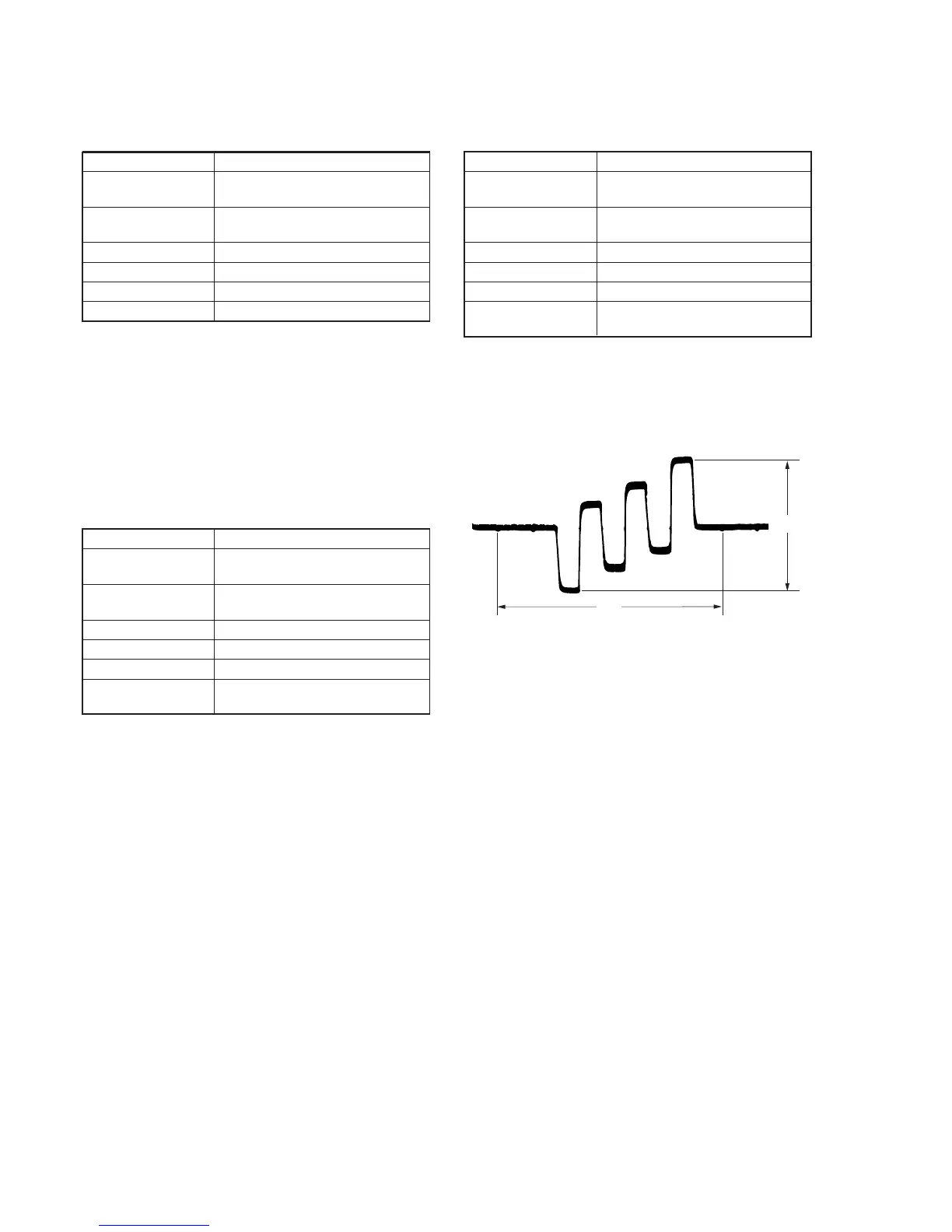
9. Decoder ACC Adjustment (VI-148 Board)
(Except AEP/UK model)
Set the decoder ACC gain.
Mode VTR stop
Signal 75% color bar (Video signal terminal
of AUDIO/VIDEO jack)
Measurement Point Pin !ª of CN9903 (DEC B-Y) on
VC-206 board
Measuring Instrument Oscilloscope
Adjustment Page D
Adjustment Address 9E
Specified Value A = 325 ± 20mV (NTSC)
A = 325 ± 20mV (PAL)
Adjusting method:
1) Select page: 0, address: 01, and set data: 01.
2) Select page: D, address: 9E, change the data and set the DEC
B-Y signal level (A) to the specified value.
3) Press the PAUSE button of the adjustment remote commander.
4) Select page: 0, address: 01, and set data: 00.
Fig. 5-3-15
 Loading...