5-22
1-5. LCD SYSTEM ADJUSTMENT
Note 1: The back light (fluorescent tube) is driven by a high voltage AC
power supply. Therefore, do not touch the back light holder to
avoid electrical shock.
Note 2: When replacing the LCD unit, be careful to prevent damages
caused by static electricity.
Note 3: Set the LCD BRIGHT to the center. Set the LCD COLOR (Menu
display) to the center.
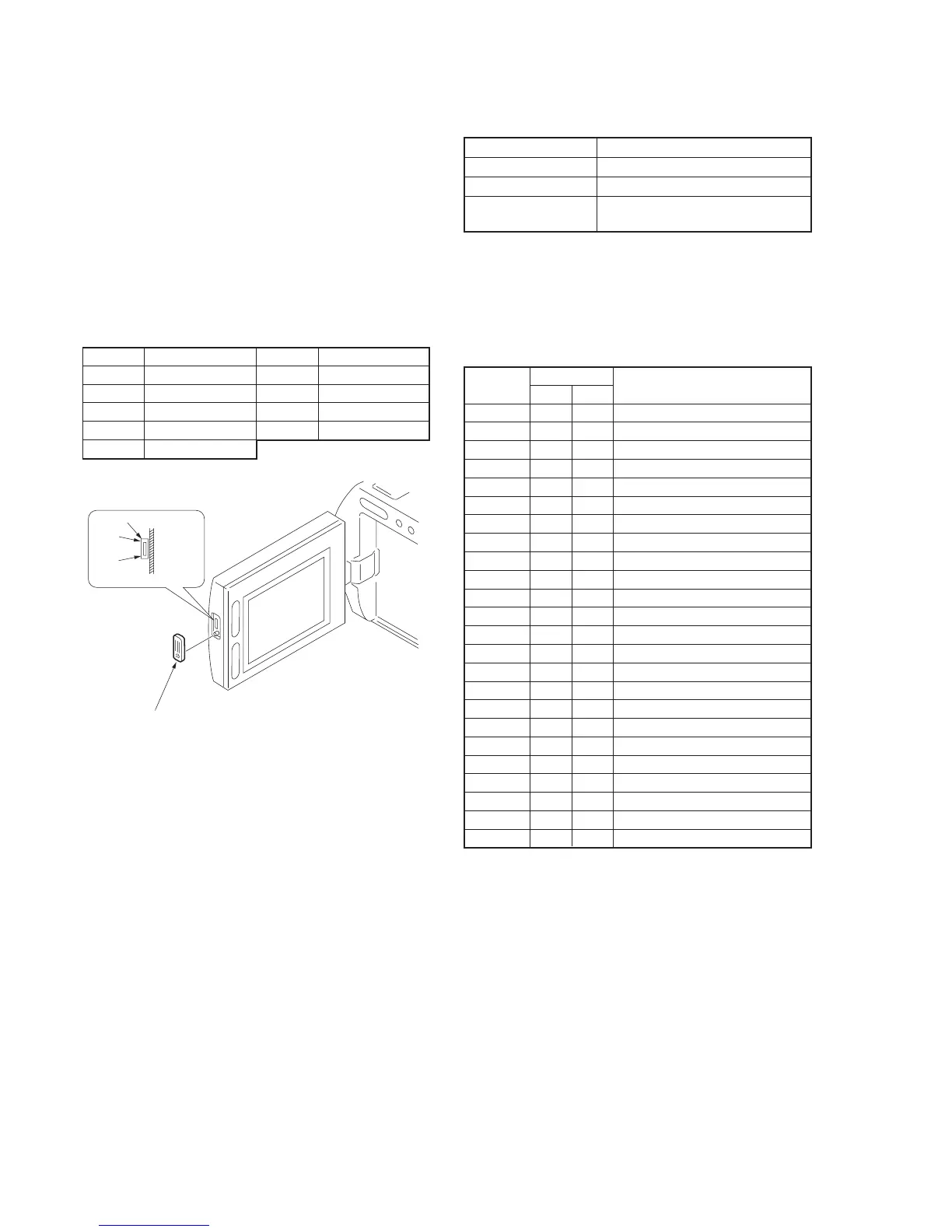
[Adjusting connector]
Most of the measuring points for adjusting the LCD display are
concentrated in the following connector. CN5501 of the PD-98 board
Connect the Measuring Instruments via the multi CPC jig (J-6082-
311-A).
The following table shows the Pin No. and signal name of the
connector.
Fig. 5-1-15
Pin No.
1
2
3
4
5
Signal Name
VR
VG
VB
PANEL COM
GND
Pin No.
6
7
8
9
Signal Name
PANEL XHD
HSY
SYF
X TEST
CN5501 (CPC)
9 pin
1 pin
PD-98
board
Remove the cover.
1. LCD Initial Data Input
Mode VTR stop
Signal Arbitrary
Adjustment Page D
Adjustment Address 60 to 67, 6A to 6F, 80 to 86, 8E, 8F,
99
Adjusting method:
1) Select page: 0, address: 01, and set data: 01.
2) Select page: D, and input the data in the following table.
Note: To write in the non-volatile memory (EEPROM), press the
PAUSE button of the adjustment remote commander each time
to set the data.
3) Select page: 0, address: 01, and set data: 00.
Address
60
61
62
63
64
65
66
67
6A
6B
6C
6D
6E
6F
80
81
82
83
84
85
86
8E
8F
99
NTSC
A0
73
C7
70
59
B0
96
00
94
E6
7A
6C
24
44
38
00
20
20
00
00
85
12
40
31
PAL
A0
73
C7
70
59
A0
96
FF
94
E6
7A
6C
24
44
38
00
20
20
00
00
E5
12
40
31
Data
Remark
White balance adjustment
White balance adjustment
Contrast adjustment
D range adjustment
V-COM level adjustment
VCO adjustment
V-COM adjustment
Fixed value
Fixed value
Fixed value
Bright adjustment
Color adjustment
Fixed value
Fixed value
Fixed value
Fixed value
Fixed value
Fixed value
Fixed value
Fixed value
Fixed value
Fixed value
Fixed value
Fixed value
 Loading...