HCD-FLX5D/FLX7D
3333
SECTION 6
ELECTRICAL ADJUSTMENTS
0 dB=0.775 V
DECK SECTION
1. The adjustments should be performed with the rated power
supply voltage unless otherwise noted.
2. The adjustments should be performed in the order given in
this service manual. (As a general rule, playback circuit ad-
justment should be completed before performing recording
circuit adjustment.)
3. The adjustments should be performed for both L-CH and R-
CH.
4. Switches and controls should be set as follows unless other-
wise specified.
• Test Tape
Tape Signal Used for
WS-48B 3 kHz, 0 dB Tape Speed Check
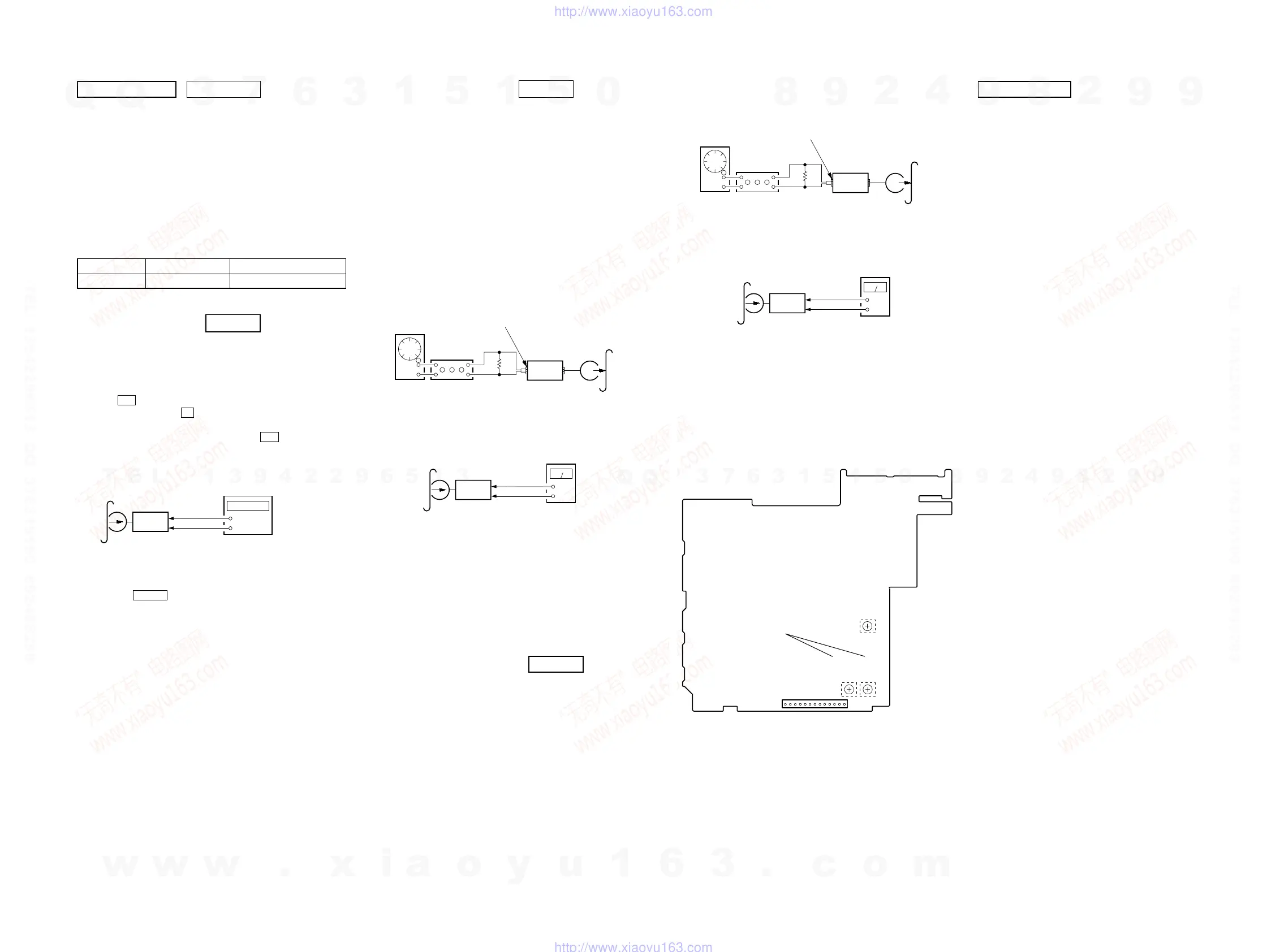
TAPE SPEED CHECK DECK B
Note: Start the Tape Speed adjustment as below after setting to the test
mode.
In the test mode, the tape speed is high during pressing the
[CD SYNC HI-DUB] button.
Procedure:
1. Press ?/1 button to turn the set ON.
2. Press three buttons x , [DISPLAY] and [CD SYNC HI-DUB]
simultaneously.
To release from the test mode, press the ?/1 button.
Mode: Playback
1. Insert the WS-48B into the deck B.
2. Press the hH button on the deck B.
3. Press the [CD SYNC HI-DUB] button in playback mode.
Then at HIGH speed mode.
4. Check so that frequency counter reads 6,000 ± 180 Hz.
5. Press the [CD SYNC HI-DUB] button.
Then back to NORMAL speed mode.
6. Check so that frequency counter reads 3,000 ± 90 Hz.
Check Location: SP RELAY board
Sample Value of Wow and Flutter: 0.3% or less W. RMS (JIS)
(WS-48B)
+
–
set
test tape
WS-48B
(3 kHz, 0 dB)
SP RELAY board
CN804 Pin
3
(GND)
SP RELAY board
CN804
Pin
2
(L-CH)
Pin
5
(R-CH)
frequency counter
REC BIAS ADJUSTMENT DECK B
Procedure:
In the MC test mode, the “REC memory mode” is convenient for
this adjustment. In the “REC memory mode” , when the REC starts
the input signal FUNCTION is switched to VIDEO automatically.
When the REC stops, the tape returns near to the recording start
position.
1. Press [VIDEO $SAT%] button to select VIDEO. (This step is
not necessary if the above test mode has already been set)
2. Insert a tape into deck B.
3. After press [REC PAUSE/START] button, press [REC
PAUSE/START] button, then rec ording start.
4. Mode: Record
5. Mode: Playback
6. Confirm the playback signal recorded in step 3 becomes ad-
justable level as follows.
If these levels are not adjustable level, adjust the RV2 (L-CH)
and RV52 (R-CH) on the SP RELAY board to repeat steps 4
and 5.
Adjustable level: Playback output of 315 Hz to playback output
of 10 kHz: ±1.0 dB
Adjustment Location: SP RELAY board
REC LEVEL ADJUSTMENT DECK B
Procedure:
In the MC test mode, the “REC memory mode” is convenient for
this adjustment. In the “REC memory mode” , when the REC starts
the input signal FUNCTION is switched to VIDEO automatically.
When the REC stops, the tape returns near to the recording start
position.
1. Press [VIDEO $SAT%] button to select VIDEO. (This step is
not necessary if the above test mode has already been set)
2. Insert a tape into deck B.
3. After press [REC PAUSE/START] button, press [REC
PAUSE/START] button, then recording start.
attenuator
set
DSP board
MD (AUDIO) (J701)
1) 315 Hz
2) 10 kHz
50 mV (
−
23.8 dB)
600
Ω
blank tape
CN-123
AF OSC
+
–
set
recorded
portion
SP RELAY board
CN804 Pin
3
(GND)
SP RELAY board
CN804
Pin
2
(L-CH)
Pin
5
(R-CH)
level meter
4. Mode: Record
5. Mode: Playback
6. Confirm the play back signal recorded in step 3 becomes ad-
justable level as follows.
If these levels are not adjustable level, adjust the RV53 (R-
CH) on the SP RELAY board to repeat steps 4 and 5.
Adjustable level:
CN804 PB level: 47.2 to 53.0 mV (−24.3 to −23.3 dB)
Adjustment Location: SP RELAY board
set
DSP board
MD (VIDEO) (J701)
315 Hz, 50 mV (
−
23.8 dB)
blank tape
CS-123
600
Ω
attenuator
AF OSC
+
–
set
recorded
portion
SP RELAY board
CN804 Pin
3
(GND)
SP RELAY board
CN804
Pin
5
(R-CH)
level meter
CN804
13
1
− SP RELAY BOARD (Conductor Side) −
REC BIAS
ADJUSTMENT
REC LEVEL
ADJUSTMENT
(L-CH)
(R-CH)
RV52
RV2
RV53
DVD SECTION
About the dicision to pass or fail of the optical pick-up block, re-
fer to “DICISION TO PASS OR FAIL OF THE OPTICAL PICK-
UP BLOCK” (see page 8)
AUTO SERVO ADJUSTMENT
After parts related to the servo circuit (RF amplifier (IC001), DSP
(IC509), motor driver (IC501), EEPROM (IC903) so on) are re-
placed, re-adjusting the servo circuit is necessary. Select “ALL” at
“1. DRIVE AUTO ADJUSTMENT” (Refer to page 27 in TEST
MODE) and adjust DVD-SL (single layer), CD and DVD-DL (dual
layer).
w
w
w
.
x
i
a
o
y
u
1
6
3
.
c
o
m
Q
Q
3
7
6
3
1
5
1
5
0
9
9
2
8
9
4
2
9
8
T
E
L
1
3
9
4
2
2
9
6
5
1
3
9
9
2
8
9
4
2
9
8
0
5
1
5
1
3
6
7
3
Q
Q
TEL 13942296513 QQ 376315150 892498299
TEL 13942296513 QQ 376315150 892498299
http://www.xiaoyu163.com
http://www.xiaoyu163.com

 Loading...