32 SR 430, SR 450
The setting gauge is not shown in
the illustration.
– Push the ignition module (1) back
– the flywheel must move freely.
: Rotate the flywheel until the
magnet poles (arrows) are next
to the ignition module (1).
– Press the ignition module against
the setting gauge.
– Tighten down the screws firmly.
– Remove the setting gauge.
– Check operation
– rotate the flywheel and make
sure it does not touch the ignition
module.
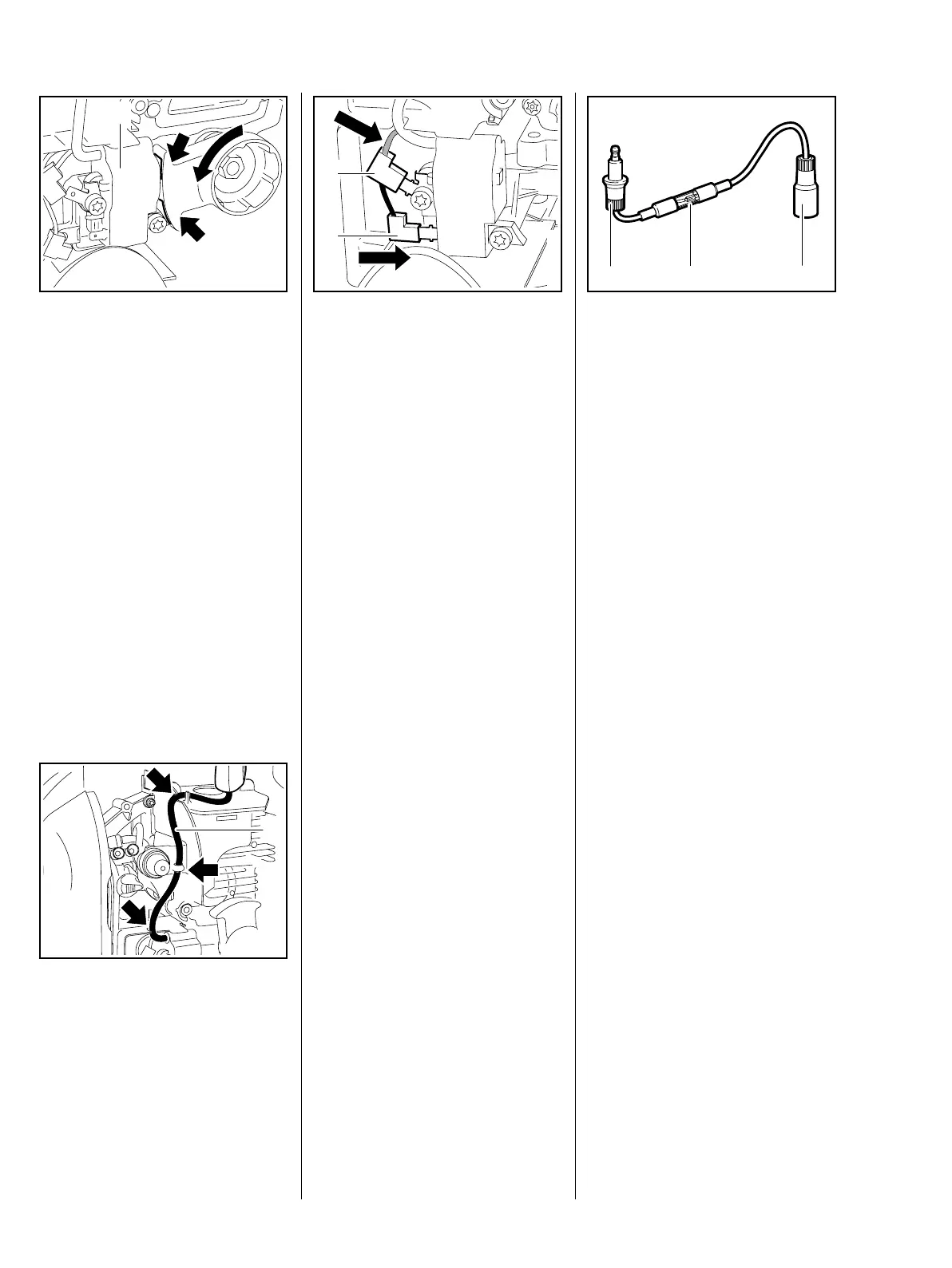
: Starting at the ignition module,
attach the ignition lead (1) to the
guides (arrows).
Position the ignition lead so that it is
not kinked at the ignition module
and not under tension.
N
S
0002RA073 TG
1
0002RA200 TG
1
: Connect the ground wire (2) and
short circuit wire (1) – make sure
the connectors are pushed fully
home.
– Push the boot onto the spark
plug.
– Reassemble all other parts in the
reverse sequence.
5.3 Testing the Ignition
Module
To test the ignition module, use
either the ZAT 4 ignition system
tester 5910 850 4503 or the ZAT 3
ignition system tester
5910 850 4520.
The ignition test refers only to a
spark test, not to ignition timing.
0002RA033 TG
1
2
Using ZAT 4 ignition system
5910 850 4503
– Before starting the test, install a
new spark plug in the cylinder
and tighten it down firmly.
: Connect spark plug boot to the
input terminal (1). Push the
tester’s output terminal (3) on to
the spark plug.
High voltage – risk of electric shock.
: Crank the engine quickly with the
rewind starter and check spark in
the tester’s window (2).
The engine may start and
accelerate during the test.
If a spark is visible, the ignition
system is in order.
If no spark is visible in the
window (2), check the ignition
system with the aid of the
troubleshooting chart, b 5.7
165RA183 TG
1
2
3
 Loading...