55SR 430, SR 450
Both versions
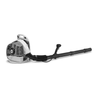
: Place the handle molding (1) in
position so that the cutout (arrow)
fits over the lever (2).
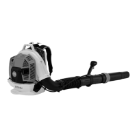
: Fit the screws (arrows).
– Check that handle molding is
properly seated.
– Insert the screws and tighten
them down firmly.
– Check operation.
– Reassemble all other parts in the
reverse sequence.
0002RA167 TG
1
2
0002RA168 TG
8.4 Valve Lever
– Remove the interlock lever and
throttle trigger, b 8.3
– Hold the valve to prevent it
popping out.
: Pull off the valve lever (1).
: Turn the valve lever (1) clockwise
and disconnect it from the rod (2).
0002RA178 TG0002RA179 TG
1
0002RA180 TG
2
1
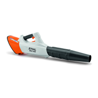
Installing
: Position the valve lever (1) so
that the guide (arrow) points in
the direction of the handle
housing.
: Push the valve lever (1) onto the
rod (2).
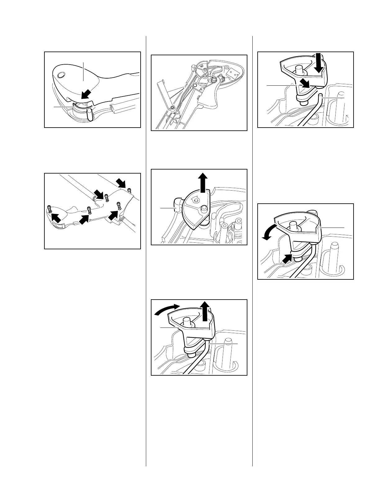
: Turn the valve lever (1)
counterclockwise as far as stop –
the rod must engage the
guide (arrow).
0002RA181 TG
2
1
0002RA182 TG
1
 Loading...