21
6 Electrical Connection
6.1 Safety Instructions
Incorrect cable connection may cause device damage or even personal
injury.
All cables must be intact, well insulated, appropriately dimensioned, and
firmly connected.
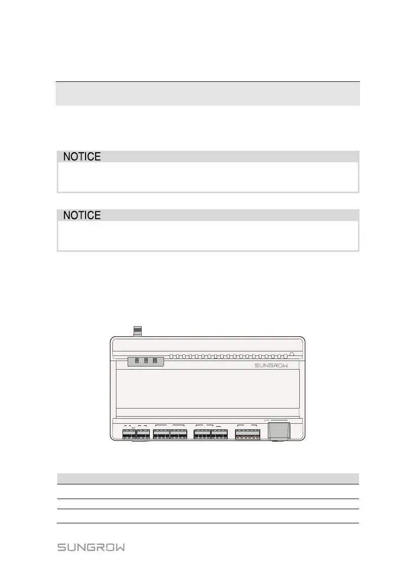
6.2 Port Introduction
External wiring terminals are located at the bottom of Logger1000, and the wiring
area is shown in the figure below.
1+ 1- 2+ 2-
AI/DI
3+ 4+3- 4-
1 2 3 4
DI DRM
0V
5 R C
A1 B1 A2 B2
RS485
A3 B3
RUN WLAN
RST
WLAN
ETH
24V
OUT
DI
+
-
24V
IN
+
-
Fig. 6-1 Wiring area
Tab. 6-1 Port description
24V OUT 24V power output
24V±5%, the max. output current: 0.5A
Switch for enabling the AI/DI function
24V IN 24V power input
24V±3%

 Loading...
