User Manual 5 Electrical Connection
37
5.3 Additional Grounding Connection
Since the inverter is a transformerless inverter, neither the negative
pole nor the positive pole of the PV string can be grounded.
Otherwise, the inverter will not operate normally.
Connect the additional grounding terminal to the protective
grounding point before AC cable connection, PV cable connection,
and communication cable connection.
The ground connection of this additional grounding terminal cannot
replace the connection of the PE terminal of the AC cable. Make sure
the two terminals are both grounded reliably.
5.3.1 Additional Grounding Requirements
All non-current carrying metal parts and device enclosures in the PV power
system should be grounded, for example, brackets of PV modules and inverter
enclosure.
The additional grounding terminal is equipped at the bottom of the inverter. Be
sure to connect this additional grounding terminal for reliable grounding and
ensure that the grounding resistance is less than 10 Ohm.
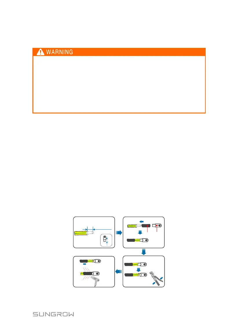
5.3.2 Connection Procedure
The additional grounding cable should be of the same cross section as the PE
wire in the AC cable.
Additional grounding cable and OT/DT terminal are prepared by customers.
1. Prepare the cable and OT/DT terminal.
 Loading...