User Manual 7 LCD Operation
67
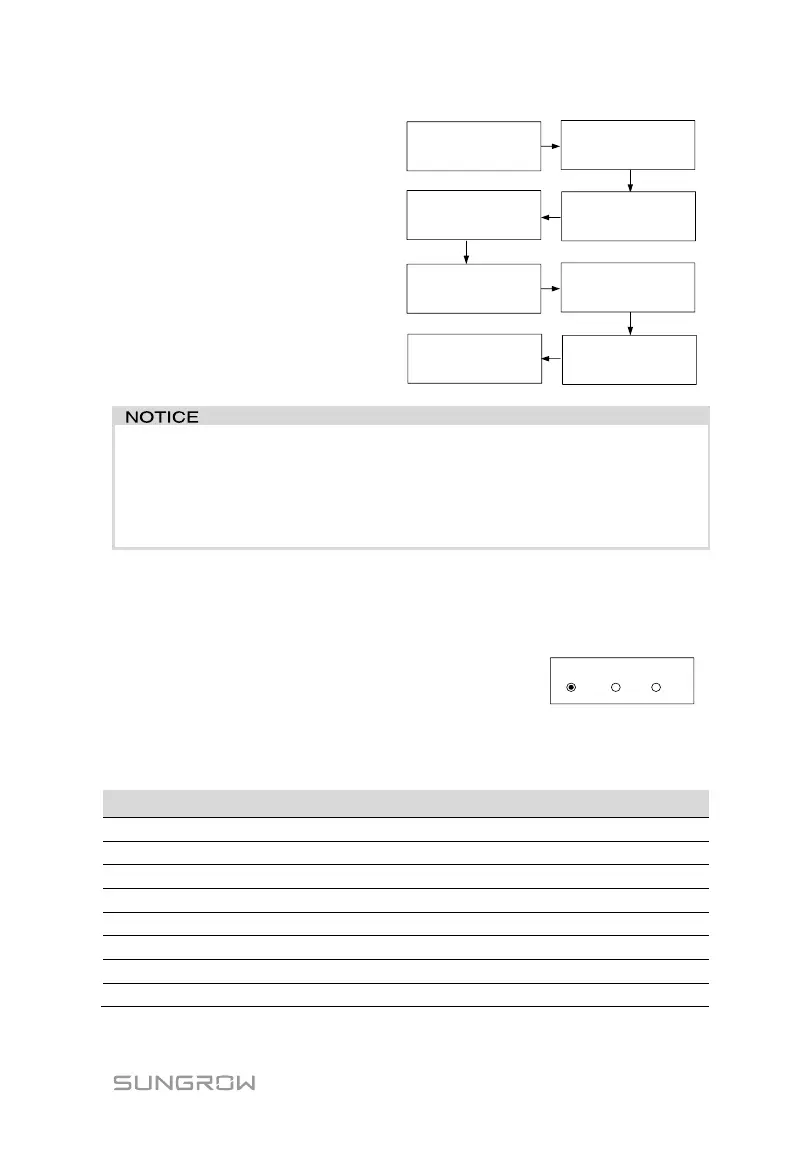
The thresholds (Imp.) are
compliant with standard CEI
0-21 and the actual values (Ril.)
are for your reference only.
Pass.: The inverter will restore
the normally used settings and
automatically reconnect to the
grid.
Fail: The inverter will report the
error 105. The inverter cannot
reconnect to the network until
the test is successfully done.
81>.S1
Imp. / Ril.
Valo. (Hz)
Tempo (s)
Risult.
50.50 / 49.99
0.10 / 0.10
Pass
81<.S1
Imp. / Ril.
Valo. (Hz)
Tempo (s)
Risult.
49.50 / 49.99
0.10 / 0.10
Pass
59.S1
Imp. / Ril.
Valo. (Hz)
Tempo (s)
Risult.
253.0 / 230.0
0.10 / 0.10
Pass
27.S1
Imp. / Ril.
Valo. (Hz)
Tempo (s)
Risult.
195.5 / 230.0
0.10 / 0.10
Pass
81>.S2
Imp. / Ril.
Valo. (Hz)
Tempo (s)
Risult.
51.50 / 49.99
0.10 / 0.10
Pass
81<.S2
Imp. / Ril.
Valo. (Hz)
Tempo (s)
Risult.
47.50 / 49.99
0.10 / 0.10
Pass
59.S1
Imp. / Ril.
Valo. (Hz)
Tempo (s)
Risult.
264.5 / 230.0
0.10 / 0.10
Pass
27.S2
Imp. / Ril.
Valo. (Hz)
Tempo (s)
Risult.
92.0 / 230.0
0.10 / 0.10
Pass
If the auto test fails or an error is triggered, the inverter cannot be
connected to the grid. Re-do the test until the result is “Pass”.
During the testing process, if an external command aimed at changing
the frequency protection thresholds is sent to the inverter, the
command will fail to act.
7.11.2 SPI Local Control
Through the local LCD setting, the over- / under-frequency protection
thresholds can be changed.
OFF (default setting): The over- / under-frequency
protection will be at wide permissive thresholds;
ON: The over- / under-frequency protection will be
at restrictive thresholds;
The following table shows the protection thresholds for different settings.
Protection Parameter Explanation
Minimum frequency 1 (F<) (Hz)
Minimum frequency 1 (F<) tripping time (s)
Minimum frequency 2 (F<<) (Hz)
Minimum frequency 2 (F<<) tripping time (s)
Maximum frequency 1 (F>) (Hz)
Maximum frequency 1 (F>) tripping time (s)
Maximum frequency 2 (F>>) (Hz)
Maximum frequency 2 (F>>) tripping time (s)
 Loading...