5 Electrical Connection User Manual
46
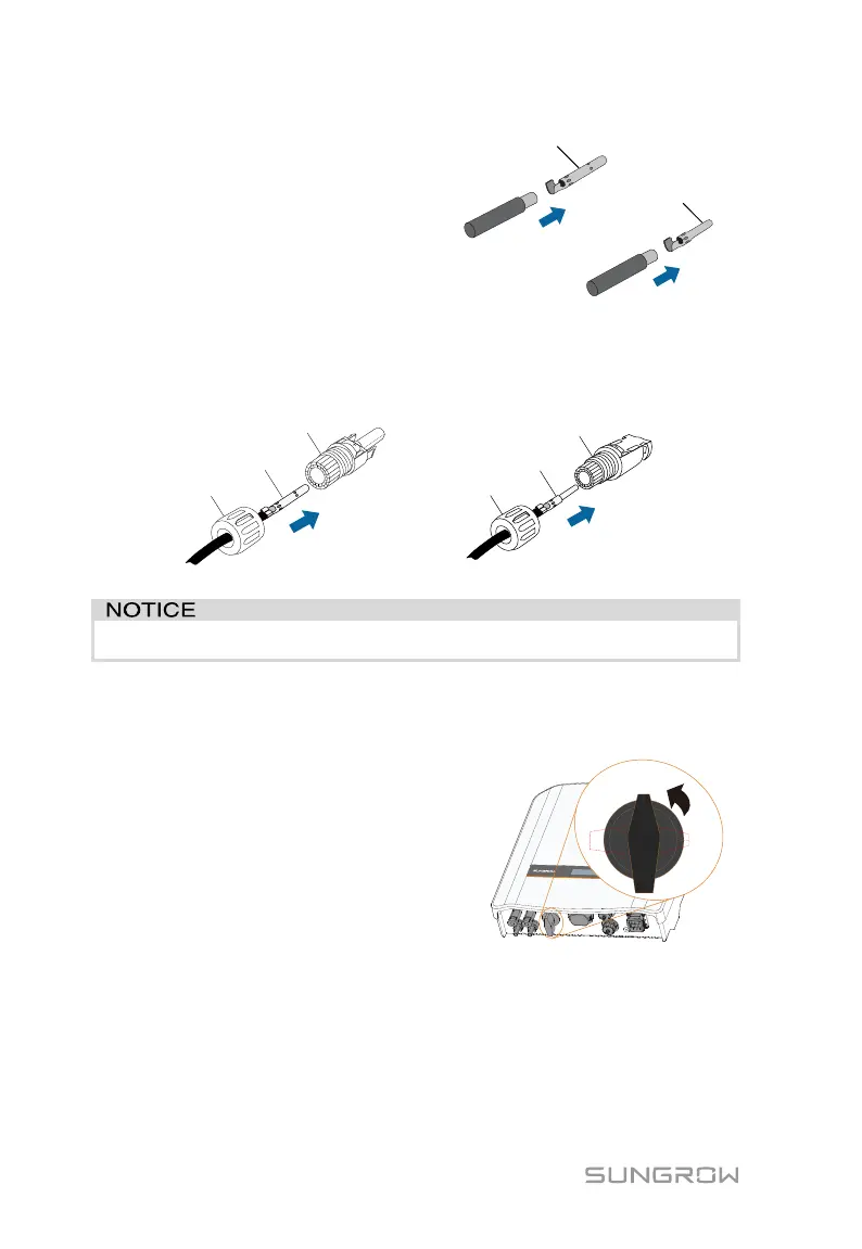
2. Assemble the cable ends
with the crimping pliers.
Positive Crimp Contact
Negative Crimp Contact
3. Lead the cable through cable gland, and insert into the insulator until it
snaps into place. Gently pull the cable backward to ensure firm
connection. Tighten the cable gland and the insulator (torque 2.5 Nm
to 3 Nm).
Crimp Contact
Positive Insulator
Cable Gland
Crimp Contact
Negative Insulator
Cable Gland
4. Check for polarity correctness.
The inverter will not function properly if any PV polarity is reversed.
5.5.3 Installing the PV Connector
Connect the inverter to PV strings according to the following procedure.
1. Rotate the DC switch to “OFF”
position.
 Loading...