2 Product Introduction User Manual
10
No. Name Description
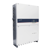
3 LCD screen
LCD screen can display current state of inverter, current
running information, history information and parameters to be
set.
Tab. 2-2 Description of LED Indicator Status
LED Status Description
“RUN”: on;
Inverter is feeding AC power to the utility grid.
“FAULT”: off
“RUN”: off;
A fault happens;
or protection function triggers.
“FAULT”: on
“RUN”: off;
Inverter is not energized;
or there is a communication error between DSP and LCD.
“FAULT”: off
“RUN”: Flicker
Warning information occurs to the inverter.
“FAULT”: OFF
2.2.4 DC Switch
DC switch is designed for safely disconnecting the DC input current if required.
The inverter works automatically when input and output meet the requirements.
Rotating DC switch to the “OFF” position will immediately cut off the flow of DC
current.
Rotate the DC switch to the “ON” position, before restarting the inverter.
2.3 Technical Description
2.3.1 Principle Description
PV strings input voltage is transmitted to DC BUS via Boost circuit.
The SG50KTL-M-20 is equipped with MPPTs for four DC inputs to ensure that the
maximum power can be utilized even in different PV modules installation
conditions.
Inversion circuit converts DC power into AC power, which will be fed into the utility
grid via five core terminals. Protective circuits are designed to guarantee inverter
safe operation and human safety.
DC switch is integrated for safe disconnection of DC current. The inverter provides
standard interface RS485 for communication. Inverters are also provided running
records display and parameters configuration via human-computer interface– LCD
display panel.

 Loading...