TB7100 Service Manual Disassembly and Reassembly 105
© Tait Electronics Limited October 2005
7.6 Reassembling the Transmitter Module
The circled numbers in this section refer to the items in Figure 7.5 on
page 104.
1. If the power connector has been replaced:
■ With the 25W board, use a Torx T10 torque-driver to tighten the
two screws
1! to 3lb·in (0.34N·m).
■ With the 50W/40W board, use a Torx T6 torque-driver to
tighten the two screws
1! to 1lb·in (0.11N·m).
2. The L-shaped gap pad
i and (with the 50W/40W board) the
rectangular gap pad
j must be replaced each time the board is
separated from the heatsink
1):
■ Remove any residue of the gap pad(s) from the underside of the
board and the heatsink.
■ Make sure that the heatsink and the heat plates are free of any dust.
■ Peel off the transparent film on one side of the L-shaped gap pad
i and evenly press the gap pad on the contact surfaces of the
heatsink.
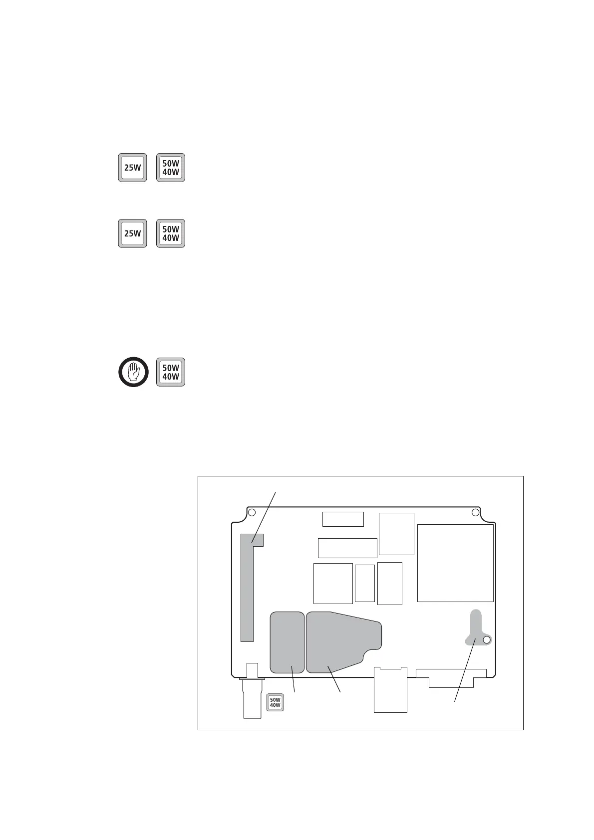
Important With the 50W/40W board, the rectangular gap pad
j
must not overlap the edge of the tin-plated copper plate
(refer to Figure 7.6).
■ Peel off the transparent film on one side of the rectangular gap pad
and evenly press the gap pad on the contact surfaces of the board.
■ Peel off the transparent film on other of the gap pad(s).
Figure 7.6 Contact surfaces on the bottom side of the board
tin-plated
copper
plate
contact surface
of rectangular
gap pad
Audio-PA area
contact surface of L-shaped gap pad

 Loading...


