82 General Information TB7100 Service Manual
© Tait Electronics Limited October 2005
6.4 Test Equipment Setup
This section describes how to set up of the test equipment for servicing the
base station. Refer to “Tools, Equipment and Spares” on page 78 for details
of the test equipment.
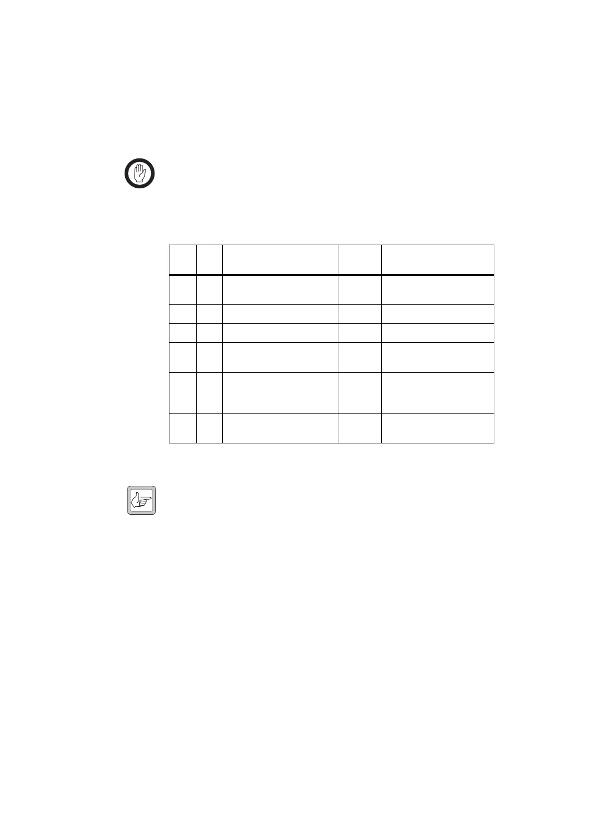
Important For testing, the base station must be linked as a line-
controlled base station and not as a repeater. Table 6.2
shows the link settings of the SI board. The optional
duplexer must be removed before testing.
Test Setup with CTU The standard test setup using the CTU is shown in Figure 6.2.
Note The CTU is described in the TBA0STU/TBA0STP Calibration
& Test Unit Operation Manual (MBA-00013-xx).
1. Connect the test PC to the P
ROG/MIC connector on the front of the
base station using the T2000-A19 and TMAA20-04 cables.
2. Connect the 25-pin S
YSTEM INTERFACE connector of the CTU to the
S
YSTEM connector of the base station using the TB7100 CTU adapter
and the 25-way D-range ribbon cable. Audio connections between
the CTU and test equipment are described in the relevant test steps.
3. Set all switches on the CTU to the off position.
4. Connect the R
X N-type connector of the base station to the output
port of the RF test set (D
UPLEX OUT).
5. Connect the T
X/ANT N-type connector of the base station to the input
port of the RF test set (RF I
N).
6. Connect the 13.8V DC power supply to the DC power connector
(labelled 12VDC) of the base station.
Table 6.2 Link settings of the SI board
Link Pins Name
Default
Position
Function
J400 3 Tx Key Source 1-2 External PTT signal to
transmitter
J500 3 Line Out Frequency Response 2-3 De-Emphasis
J501 3 Line In Frequency Response 2-3 Pre-Emphasis
J502 3 Tx Audio Source 1-2 External audio line in to
transmitter
J503 3 Rx Audio Destination 2-3 Received audio sent to
balanced and unbalanced
external outputs
J507 3 Line In Destination 2-3 AUDIO_TAP_IN.
The Tx audio tap point

 Loading...


