TB7100 Service Manual Functional Description 29
© Tait Electronics Limited October 2005
Bias Ramp-up
The steady-state final-stage bias level is supplied by an 8-bit DAC
programmed prior to ramp-up but held to zero by a switch on the DAC
output under the control of a
TX INHIBIT signal. Bias ramp-up begins upon
release by the
TX INHIBIT signal with the ramping shape being determined by
a low-pass filter. Owing to power leakage through the PA chain, ramping
the bias takes the PA output power from less than –10 dBm to approximately
25dB below steady-state power.
Power Ramp-up The power ramp signal is supplied by a 13-bit DAC that is controlled by
custom logic. The ramp is generated using a look-up table in custom logic
memory that is played back at the correct rate to the DAC to produce the
desired waveform. The ramp-up and ramp-down waveforms are produced
by playing back the look-up table in forward and reverse order respectively.
For a given power level the look-up table values are scaled by a steady-state
power constant so that the ramp waveform shape remains the same for all
power levels.
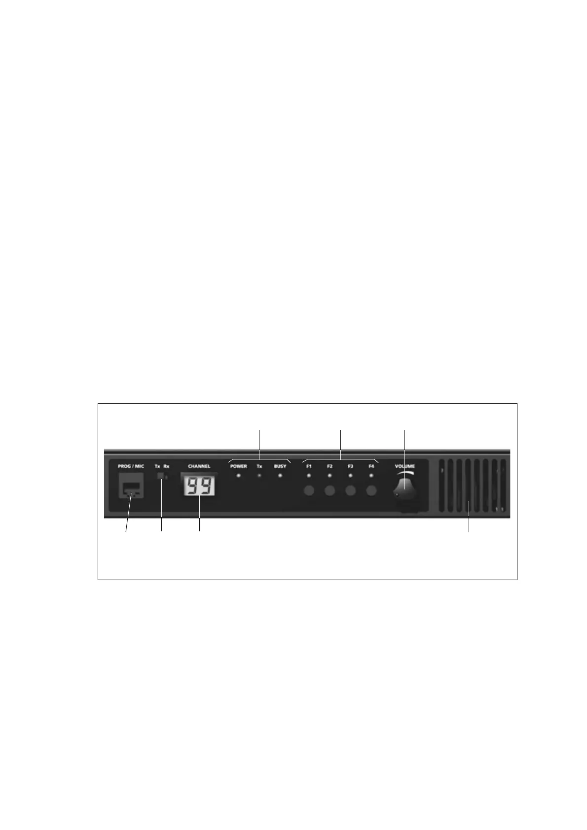
3.3 User Interface Operation
This section describes the functioning of the user interface.
Figure 3.5 shows the controls and indicators of the user interface.
The user interface provides a panel consisting of:
■ two digit, seven-segment LCD display
■ four programmable function keys
■ LED indicators
■ volume control
■ internal speaker
■ PROG/MIC connector
■ TX/RX switch
Figure 3.5 User interface
volume controlfunction keys and LEDs
speaker
status LEDs
LCD
display
Tx/Rx
switch
programming/
microphone
connector

 Loading...


