TB7100 Service Manual Disassembly and Reassembly 101
© Tait Electronics Limited October 2005
7.2 Replacing the UI Board
Removal 1. Remove the volume knob by pulling slowly but firmly. The knob is
a friction fit and can leave the collet behind on the shaft. If this
happens, remove the collet from the shaft and place inside the knob.
2. Disconnect the speaker connector
b.
3. Use a Torx T10 screwdriver to remove the three screws
c together
with the spring washers and flat washers.
4. Insert the card remover tool (220-02034-xx) from the tool kit
(TBA0ST2), or a small flat-bladed screwdriver into the two small
holes at the bottom of the UI board. Lever the board completely off
the spring clips
d.
5. Carefully slide the UI board towards the rear of the base station until
the volume-control shaft clears the front panel. Lift the UI board clear
of the chassis.
6. Disconnect the two Micro-MaTch connectors
e.
Fitting 1. Plug the two Micro-MaTch connectors e into the UI board.
The Micro-MaTch connector for the transmitter is closest to the
edge of the UI board.
2. Align the volume-control shaft
with the hole in the front panel, also
align the programming/microphone connector and function buttons
as the board is slid into place.
3. Gently slide the UI board into position so that the spring clips
d are
engaged. Press firmly around the spring clips to ensure they are
engaged fully.
4. Use a Torx T10 screwdriver to fasten the three screws
c to 4.5lb·in
(0.5N·m).
5. Plug the speaker connector
b into the UI board.
6. Fit the volume knob onto the shaft and press firmly until fully seated.
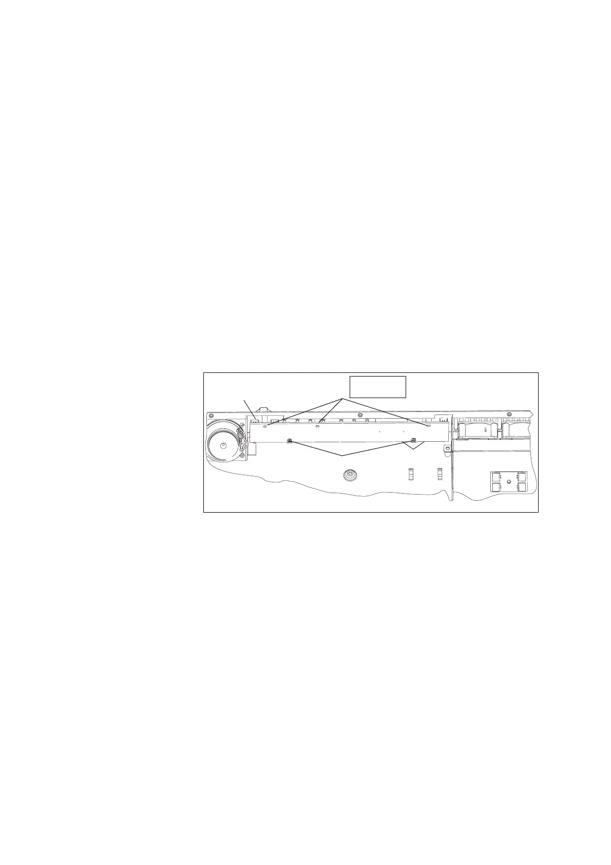
Figure 7.2 Removing the UI board
e
d
c
b
Cables not shown.
Torx T10
4.5lb·in (0.5N·m)

 Loading...


