TB7100 Service Manual Disassembly and Reassembly 107
© Tait Electronics Limited October 2005
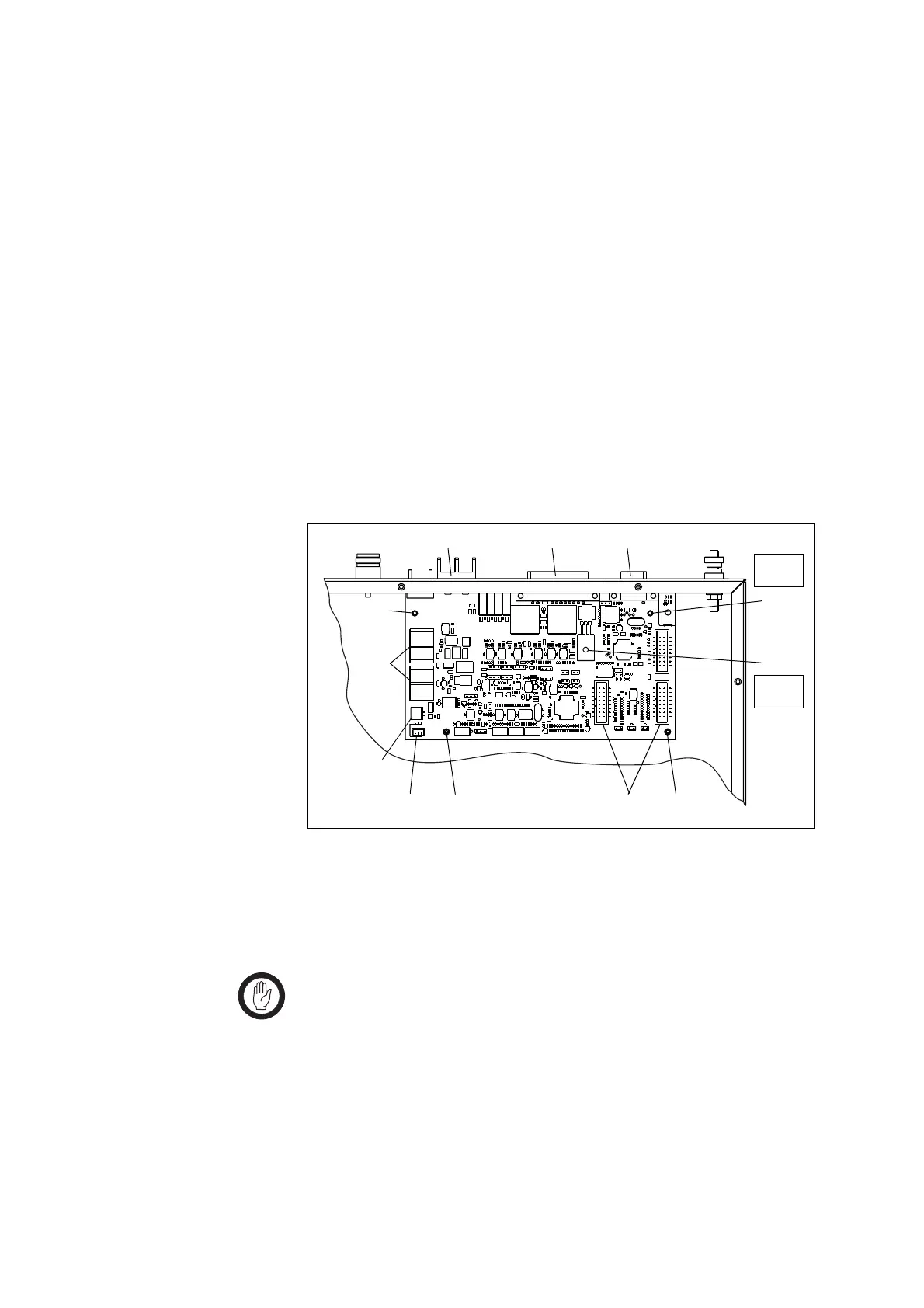
7.7 Replacing the SI Board
Removal 1. Disconnect the system interface cables e to the transmitter and the
receiver, the fan control cable
f, and the temperature sensor cable g,
and move them to one side.
2. Remove the DC power cables
h and move them to one side.
Note the connection positions.
3. Use a Torx T10 screwdriver to remove the two screws
j.
Use a PZ1 Pozidriv screwdriver to remove the screw
i on the
heatsink of U406.
4. Carefully lift the front of the SI board off the spring clips
1).
5. Carefully slide the SI board towards the front of the base station until
the connectors
b, c and d clear the rear panel. Lift the SI board
clear of the chassis.
Fitting 1. Slide the SI board into the tray chassis by fitting the connectors b, c
and
d into the rear panel.
2. Press down firmly on the front of the SI board to engage the two
spring clips
j.
Important Make sure that the thermal pad is fitted under and the
plastic insulating washer is fitted on U406.
3. Use a torque-driver to fasten the two screws
j (Torx T10) the screw
i (PZ1) on the heatsink of U406 to 4.5lb·in (0.5N·m).
4. Connect the system interface cables
e to the transmitter and the
receiver, the fan control cable
f, the temperature sensor cable g, and
the DC power cables
h.
Figure 7.7 Replacing the SI board
g
h
b
c d
Torx T10
4.5lb·in
j
j
i
1)
1) ef
PZ1
4.5lb·in

 Loading...


