TB7100 Service Manual Mechanical Design 15
© Tait Electronics Limited October 2005
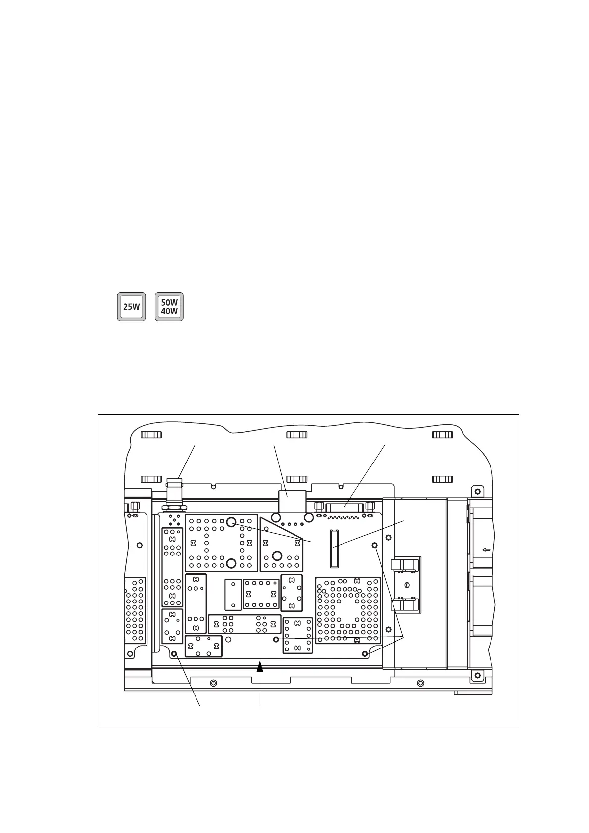
2.3 Receiver Module
The receiver module is mounted in the front left of the tray with five Torx
T10 screws
g.
The receiver module is a printed circuit board in SMT design with
components on the top and bottom sides. A digital board is reflow-soldered
to the receiver. Most components are shielded by metal cans.
There are different boards for each frequency band and each RF output
power configuration.
The RF
b, DC power c, auxiliary d, and user interface f connectors are
located on the bottom side of the board. The internal options connector
e
and a factory connector (not shown) for factory use are located on the top
side of the board.
For compliance reasons, there are different variants of the receiver module
for use in the 25W and 50W/40W base stations. The 25W version has a
white DC power connector
C and the 50W/40W version has a black DC
power connector.
For more information on the connectors, refer to “Connections” on
page 63.
Figure 2.3 Receiver module
g
g
f
b
cd
g
e

 Loading...


