14 Mechanical Design TB7100 Service Manual
© Tait Electronics Limited October 2005
2.1 Tray
The 1U tray consists of a mild steel folded chassis and a flat cover (not
shown) which is fastened to the chassis with 15 Torx T10 screws. The tray
can be fitted into a standard 19 inch rack or cabinet using the two rack
mounting brackets.
The front panel has holes to accommodate the controls and the
microphone/programming connector of the UI board.
The rear panel has holes to accommodate the connectors and the fuse holder
of the SI board, the antenna connectors, and a ground terminal.
For more information on the connections, refer to “Connections” on
page 63.
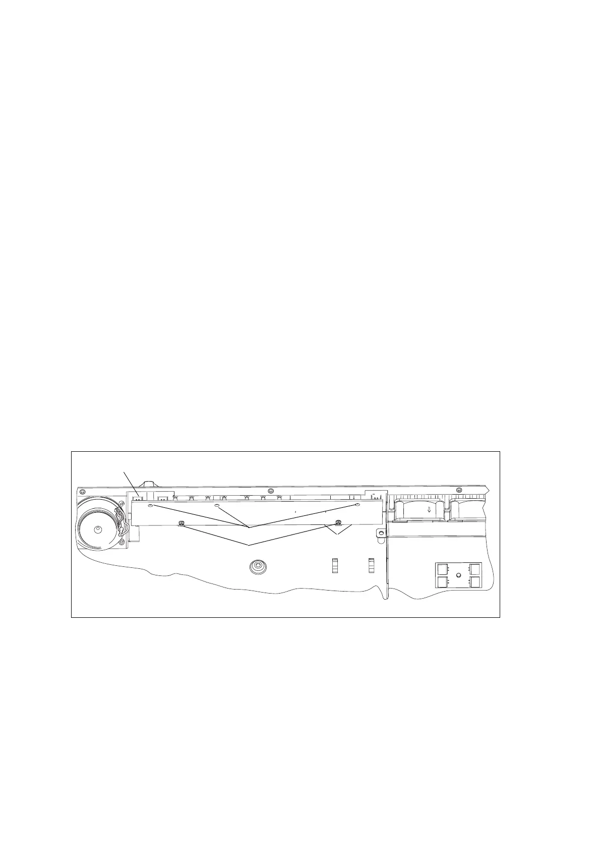
2.2 UI Board
The UI board is mounted behind the front panel with three Torx T10
screws
c and two spring clips D. The UI board is connected to the
transmitter and receiver modules via the two Micro-MaTch connectors
e
and the two UI cables (not shown). The UI board also has a speaker
connector
b.
A volume knob is fitted to the shaft of the volume-control potentiometer.
Figure 2.2 UI board
e
d
c
b
Cables not shown.

 Loading...


