Maintenance
6–46
TDS 200 Series Digital Oscilloscope Service Manual
The instrument runs an extensive self diagnostics at every power-on. Running the
diagnostics from the service menu will provide no additional information than
the power-up screen and therefore is not needed. The menu selections are only
used during manufacturing of the instrument.
Use these techniques to troubleshoot other parts of the instrument.
Input Connections. Follow these steps to troubleshoot the input connections only
if the following condition is true: the instrument appears to function normally in
every way except you have determined that an input signal is not getting into the
instrument as expected.
1. Remove the rear cover using the procedure Rear Case on page 6–14.
2. Check that the coaxial connections to the back side of the BNC connectors
are intact. Use the DMM to measure continuity from the BNC connector to
the end of the coaxial cable where it attaches to the main board.
3. If no problem is found and the trouble persists, the main board is probably
defective in some way that the internal diagnostics cannot detect. Replace it.
Error Log. Failures that occur during the power-up diagnostics place an entry in
the error log. The error log list can be accessed anytime by pressing the
UTILITY button and selecting Error Log. Table 6–3 lists the possible error codes
and possible causes.
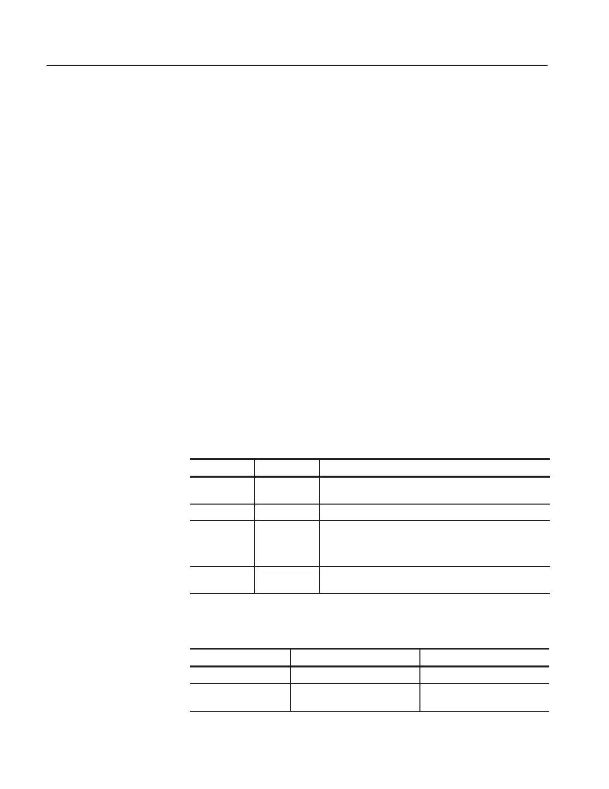
Menu Settings Comments
System
Status
Displays the system menus
Do Self Cal Performs a self calibration
Error Log Displays a list of any errors logged
This list is useful when contacting a Tektronix Service Center
for help troubleshooting problems
Service Displays the service menus for adjustment procedures and
diagnostics
Table 6–3: List of error codes
Error code Description Probable cause
0 DI Diagnostics internal error Contact Tektronix
4 DI CH1 diagnostics failed Main board or power supply
failure
Diagnostics
Other Troubleshooting

 Loading...


