Maintenance
6–22
TDS 200 Series Digital Oscilloscope Service Manual
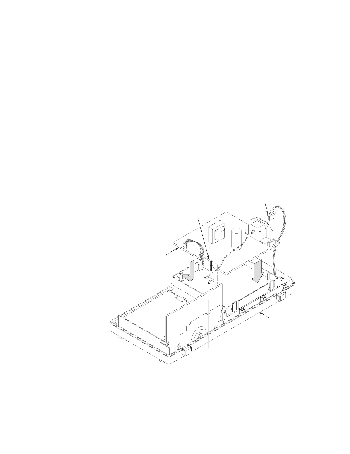
Installation. Use this procedure to install the power supply module. Refer to
Figure 6–14.
1. Place the power supply module into the inner chassis, placing the board
under the three tabs at the top of the inner chassis.
2. Snap the bottom of the module into place.
3. Reconnect the following wires.
a. The line cord ground wire on the main board at J602 or J101.
b. The seven-conductor ribbon cable on the main board at J131.
c. The two-conductor backlight cable on the power supply module.
4. Use the installation procedures for each module removed to reassemble the
instrument.
Front case
Line cord
ground wire
Seven-conductor
ribbon cable
Two-conductor
backlight cable
Power supply module
Figure 6–14: Installing the power supply module

 Loading...


