Maintenance
6–28
TDS 200 Series Digital Oscilloscope Service Manual
5. Use the installation procedures for each module removed to reassemble the
instrument.
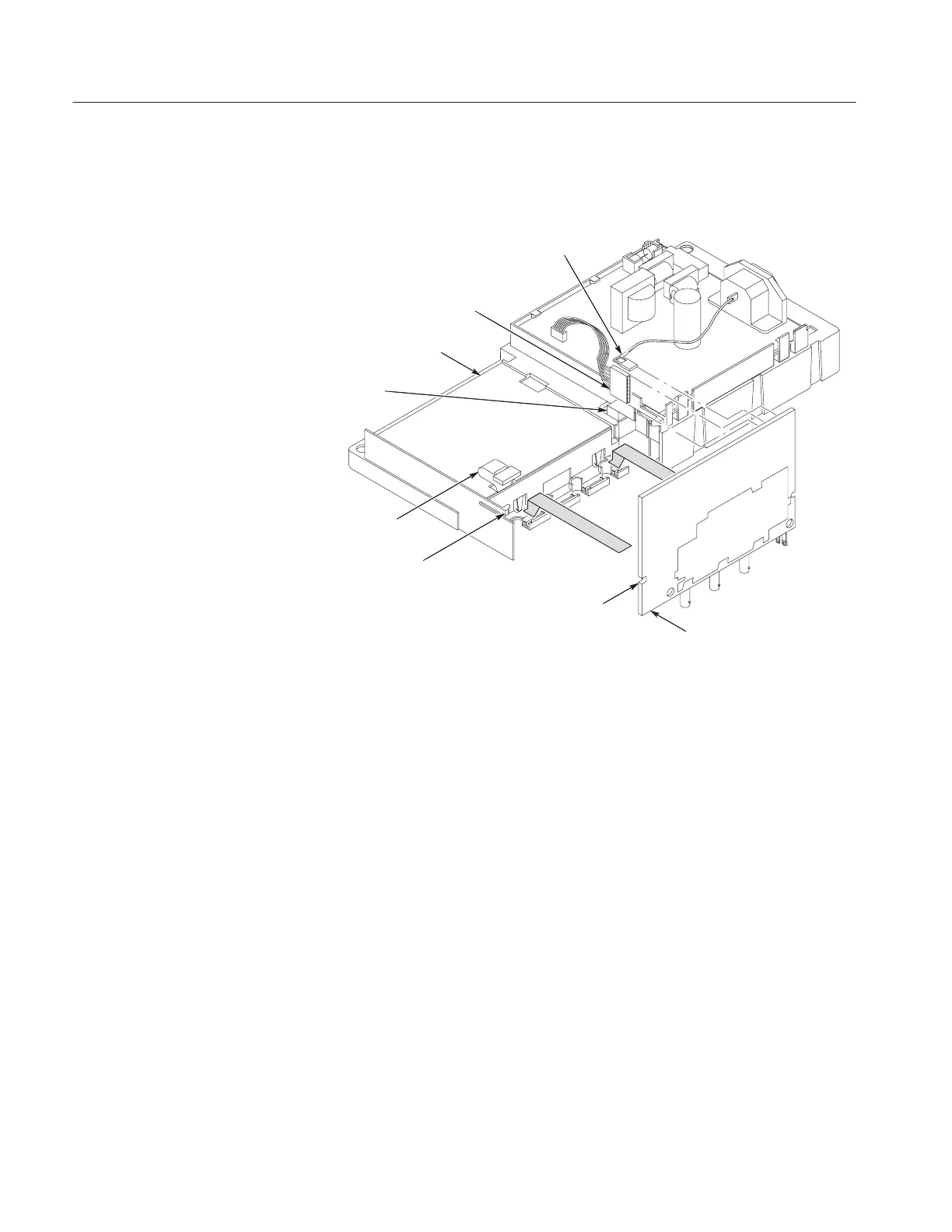
Line cord ground wire
Power supply
ribbon cable
Internal chassis
Board guides
Front panel cable
Display
module ribbon
cable
Main
board
Cutout
Figure 6–18: Main board installation
You will need a torque-limiting Torx T-15 screwdriver and a flat-blade
screwdriver for this procedure.
Removal. First remove the handle, power button, and rear case using the
procedures on pages 6–12, 6–13, and 6–14. Then, use the following procedure to
remove the display module.
1. Remove the entire internal assembly from the front case using the procedure
on page 6–24.
2. Disconnect the display module ribbon cable at J202 or J102 on the main
board by pulling straight up from the connector. Refer to Figure 6–17.
3. Disconnect the backlight cable from the power supply module. Refer to
Figure 6–14.
4. Slightly bend the two securing tabs on the left side of the display module and
lift the left side up until it clears the tabs. Then slide the display to the left
until the right-side tabs are disengaged. Refer to Figure 6–19.
Display Module

 Loading...


