Maintenance
6–30
TDS 200 Series Digital Oscilloscope Service Manual
6. Reconnect the backlight cable to the power supply module. Refer to
Figure 6–14.
7. Place the entire internal assembly into the front cover. Refer to Figure 6–16.
8. Use the installation procedures for each module removed to reassemble the
instrument.
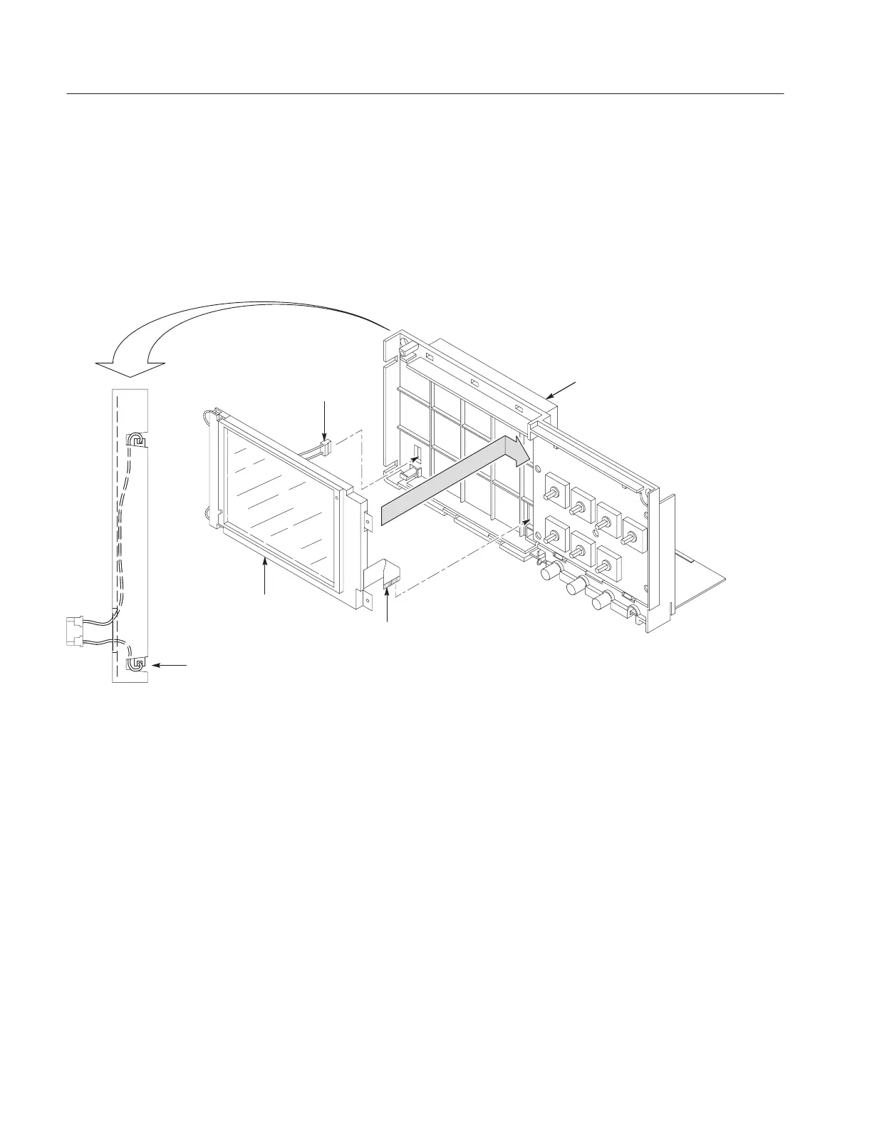
Internal chassis
Backlight cable to
power supply
module
Ribbon cable to
main board
Display module
Do not pinch backlight cable
when installing the display module.
Left side view of
internal chassis
Figure 6–20: Installing the display module
You will need a torque-limiting Torx T-15 screwdriver and a flat-blade
screwdriver for this procedure.
Removal. First remove the handle, power button, and rear case using the
procedures on pages 6–12, 6–13, and 6–14. Then, use the following procedure to
remove the front panel module.
1. Remove the entire internal assembly from the front case using the procedure
on page 6–24.
2. Disconnect the front panel ribbon cable at J200 on the main board. Refer to
Figure 6–17.
Front Panel Module

 Loading...


