Maintenance
TDS 200 Series Digital Oscilloscope Service Manual
6–27
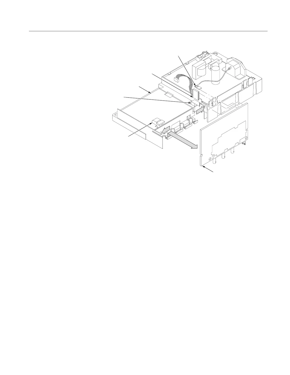
Line cord ground wire
Internal chassis
Main
board
Display
module ribbon
cable
Front panel cable
Power supply
ribbon cable
Figure 6–17: Main board removal
Installation. Use this procedure to install the main board module. Refer to
Figure 6–18.
1. Working from the bottom of the internal chassis, place the front of the main
board module into the slots on the internal chassis (near the BNC connec-
tors).
2. Keeping the module in place, press the board into place so that the securing
tabs lock onto the bottom of the board. Note that there are two board guides
on the chassis that must match the cutouts on the main board.
3. Reconnect the following wires on the main board. Refer to Figure 6–17.
a. The line cord ground wire at J602 or J101 and the seven-conductor
ribbon cable at J131 from the power supply module.
b. The ribbon cable at J603 or J103 from the front panel module.
c. The ribbon cable at J202 or J102 from the display module.
4. Place the entire internal assembly (housing all of the boards and the display
screen) into the front case as shown in Figure 6–16.

 Loading...


