BAS-SVX04A-EN • Wireless Zone Sensor 31
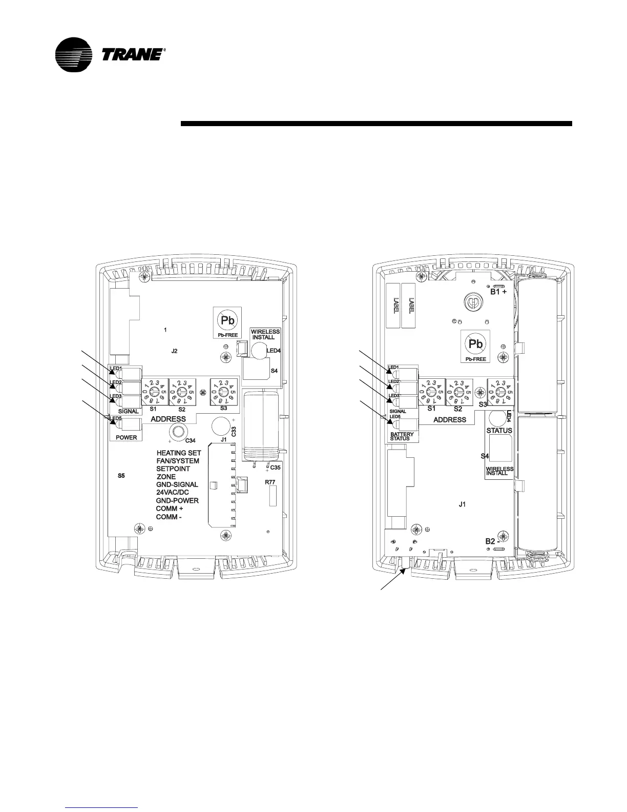
LED Operation
The sensor and receiver each have four LEDs (LED1, LED2, LED3, and LED5). The
sensor also has a Test button (S5). See Figure 17 for their locations.
Operation, Maintenance, and
Troubleshooting
Figure 17. Wireless zone sensor set components with base plates removed
Receiver
Sensor
LED1
LED2
LED3
LED5
S5
LED1
LED2
LED3
LED5

 Loading...