32 Wireless Zone Sensor • BAS-SVX04A-EN
Operation, Maintenance, and Troubleshooting
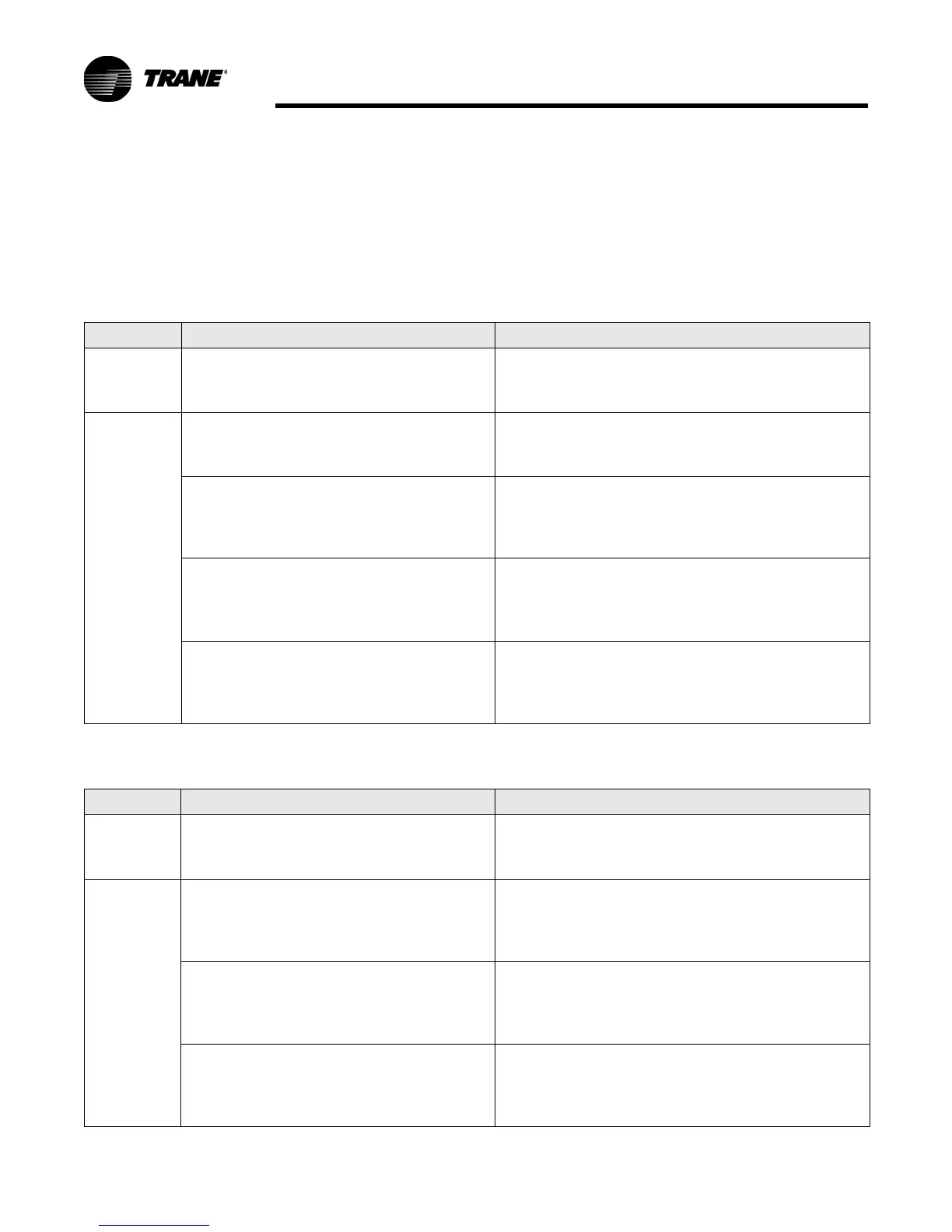
Signal Quality Test
Pressing the Test button (S5) on the sensor initiates a signal quality test. LED1,
LED2, and LED3 respond by indicating excellent, marginal, or poor signal quality.
The LEDs can be observed on both the sensor (Tab l e 3 ) and the receiver (Tabl e 4 ).
Table 3. Signal quality: LED1, LED2, LED3 on the sensor
User action LED display Indicates...
None LED1: Off
LED2: Off
LED3: Off
Normal state
• No Test button press.
Press Test
button (S5)
LED1: Off
LED2: Off
LED3: Off
Associated; no communication with receiver
• Associated, but no signal from the receiver after
pressing Test button.
LED1: On
LED2: On
LED3: On
Displays for 5 seconds, then constantly Off
Excellent signal quality
• Adequate signal margin for reliable communication.
LED1: Off
LED2: On
LED3: On
Displays for 5 seconds, then constantly Off
Marginal signal quality
• Reduced battery life is likely.
• Consider moving the sensor or receiver to a better
location.
LED1: Off
LED2: Off
LED3: On
Displays for 5 seconds, then constantly Off
Poor signal quality
• Unreliable communication.
• Strongly recommend moving the sensor or receiver to a
better location.
Table 4. Signal quality: LED1, LED2, LED3 on the receiver
User action LED display Indicates...
None LED1: Off
LED2: Off
LED3: Off
Normal state
• No Test button press.
Press Test
button (S5)
on the sensor
LED1: On
LED2: On
LED3: On
Displays for 5 seconds, then constantly Off
Excellent signal quality
• Adequate signal margin for reliable communication.
LED1: Off
LED2: On
LED3: On
Displays for 5 seconds, then constantly Off
Marginal signal quality
• Reduced battery life is likely.
• Consider moving the sensor or receiver to a better
location.
LED1: Off
LED2: Off
LED3: On
Displays for 5 seconds, then constantly Off
Poor signal quality
• Unreliable communication
• Strongly recommend moving the sensor or receiver to a
better location

 Loading...