40 Wireless Zone Sensor • BAS-SVX04A-EN
Operation, Maintenance, and Troubleshooting
Measuring Output Resistance
To measure the resistance of the receiver outputs:
1. Make sure the black wire (GNS-SIGNAL) and the yellow wire (GND-POWER)
are grounded (see Figure 8, p. 22 or Figure 9, p. 23 for wiring diagrams).
2. Make sure the receiver is powered up.
3. Disconnect the SETPOINT wire (red) and the ZONE wire (white) from the host
unit controller.
4. Measure resistance between the grounded GND-SIGNAL wire and either the
SETPOINT or ZONE wire. Compare resistance measurements to those
presented in
Tab l e 10.
5.
End-of-Range Temperature Values
The end-of-range temperature limits of the receiver are 32°F to 122°F (0°C to
50°C). The receiver cannot replicate temperature values outside this range. If the
sensor transmits a temperature value to the receiver that is out of the receiver’s
replication range, the receiver will “freeze” the output at the end-of-range values.
This value will remain frozen until the transmitted temperature moves to
between the end-of-range temperature limits.
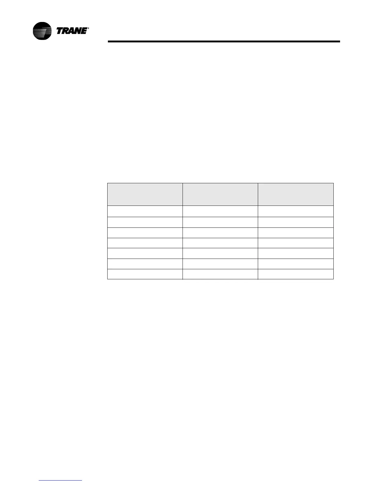
Table 10. Receiver resistance table
Zone or Setpoint
Te m pe ra tur e
Nominal Zone
Temperature output
resistance
Nominal Space
Temperature Setpoint
output resistance
55°F (12.8°C)
17.47 kΩ
812 Ω
60°F (15.6°C) 15.3 kΩ 695 Ω
65°F (18.3°C) 13.49 kΩ 597 Ω
70°F (21.1°C) 11.9 kΩ 500 Ω
75°F (23.9°C) 10.5 kΩ 403 Ω
80°F (26.7°C 9.3 kΩ 305 Ω
85°F (29.4°C) 8.25 kΩ 208 Ω

 Loading...