155
Trim system
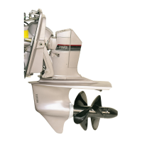
8. After all adjustments are made, tighten the trim
sender bracket hold down screw. Be sure the sending
unit does not move when the bracket is tightened.
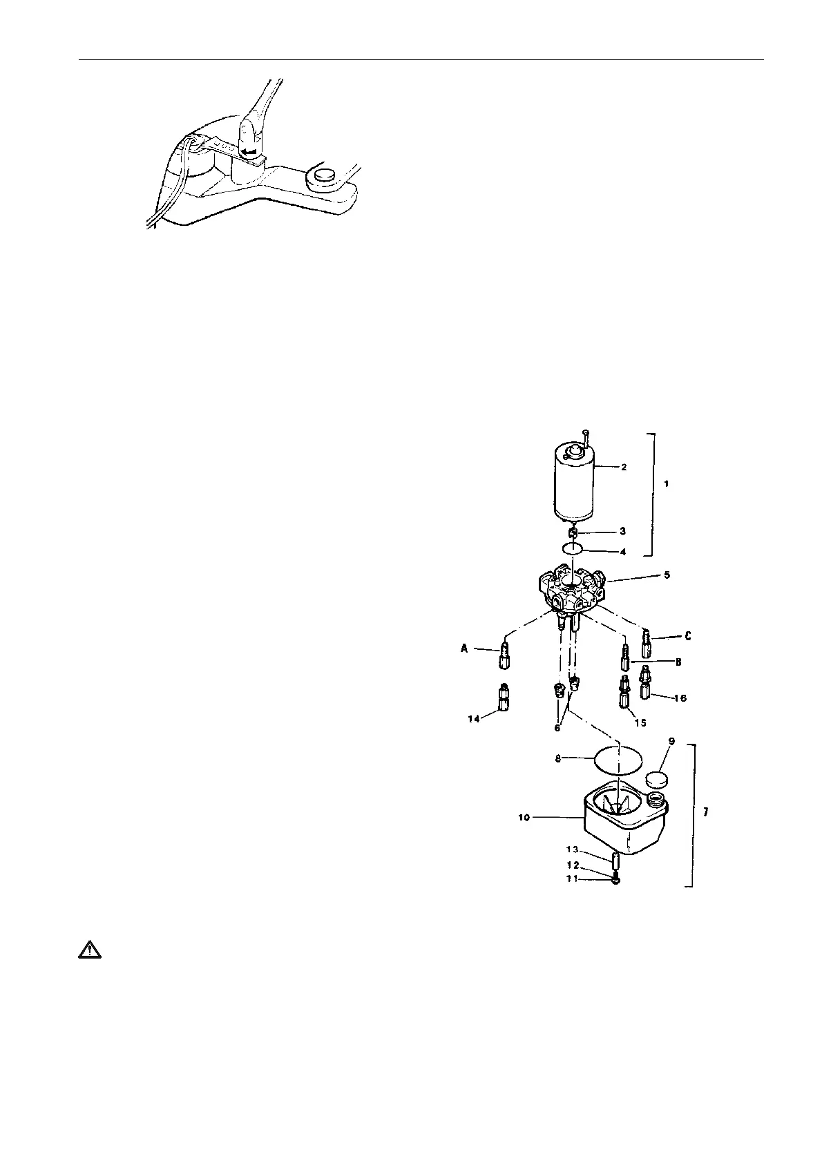
The power trim pump
The parts illustrated are those available as replace-
ment parts or complete assemblies. The following in-
structions cover the replacement of parts making up
the trim pump unit.
1 Motor assembly
2 Motor, incl. mounting studs
3 Coupling
4 O-ring
5 Adapter and basic pump assembly
1)
6 Filter
7 Reservoir assembly
8 Reservoir seal
9 Reservoir cap
10 Reservoir
11,12,13 Screw, spacer, O-ring assy
14 Thermal relief valve
1)
15 High pressure relief valve
1)
16 Low pressure relief valve
1)
A B C Original factory fitted valve assy
1)
Non-serviceable part. Replace as complete unit.
Note! Do not disassemble the valve or adapter as-
semblies, as this will disturb the factory settings and
may cause pump malfunction.
WARNING! Use great care when working with
this hydraulic system. Be sure your work area is
clean. Do not allow dirt to enter the system. Use
lint-free rags. Fill with clean recommended oil
only.
 Loading...