EasyManuals Logo

Volvo Penta AQUAMATIC 290 User Manual

Volvo Penta AQUAMATIC 290
181 pages
To Next Page IconTo Next Page
To Previous Page IconTo Previous Page
Page #170 background imageLoading...
Page #170 background image
167
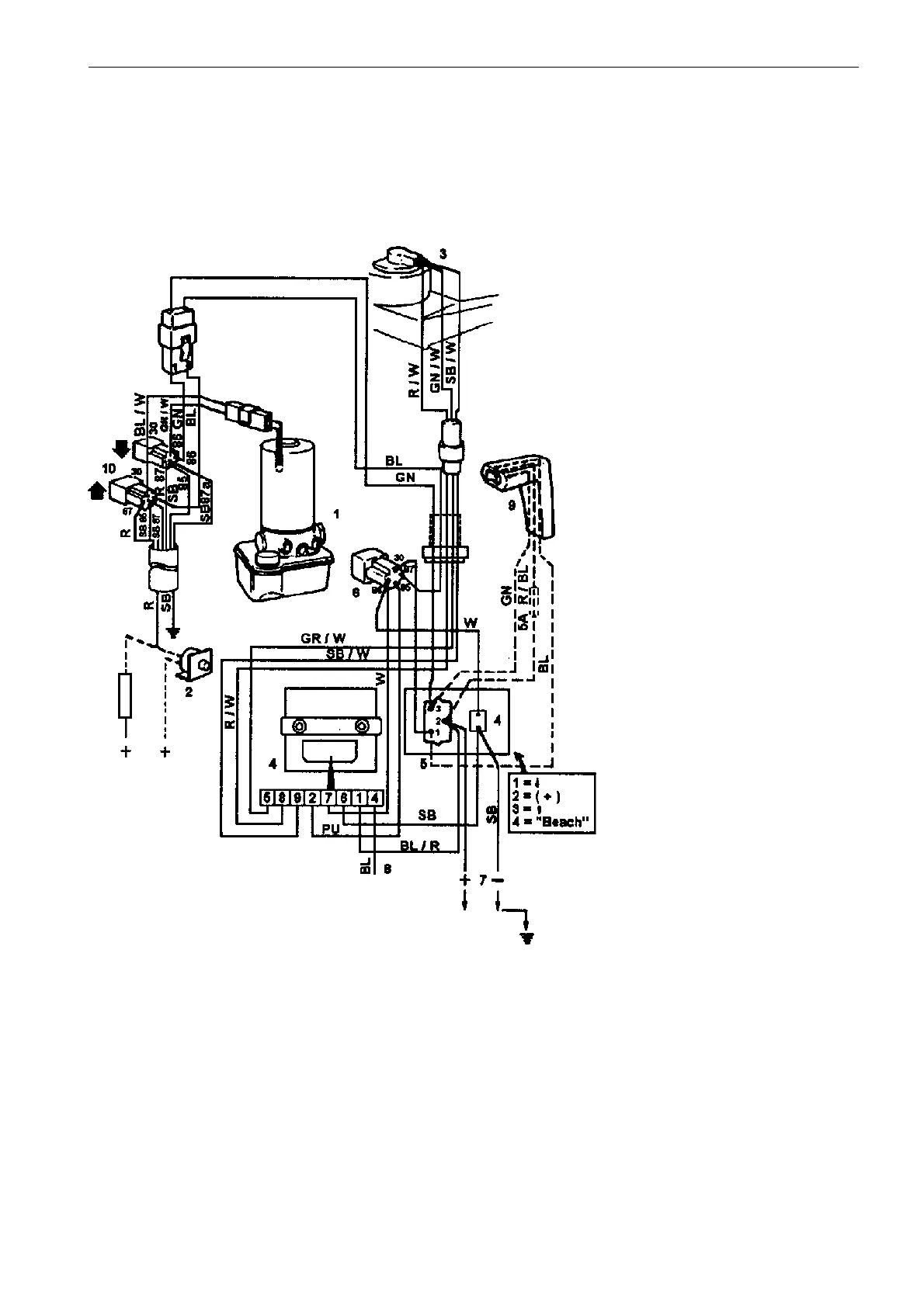
Electrical wiring diagrams
Models 290, SP and DP, Power trim
Later model
1. Oil pump
2. Fuse 55 amps
3. Trim sender
4. Trim indicator
5. Switch
6. Switch-relay, position ”Beach”
7. Connection instrument panel
8. Instrument lighting
9. Throttle hook-up (optional)
10. Relays the arrows in the electric wiring
diagram refer to the trimming function up/
down.
Cable colour codes
R = red
SB = black
GN = green
BL = blue
W = white
R/W = red/white
GN/W = green/white
SB/W = black/white
BL/R = blue/red
PU = purple
BL/W = blue/white
Cable area 1,5 mm
2

Table of Contents

Questions and Answers:

Question and Answer IconNeed help?

Do you have a question about the Volvo Penta AQUAMATIC 290 and is the answer not in the manual?

Volvo Penta AQUAMATIC 290 Specifications

General IconGeneral
BrandVolvo Penta
ModelAQUAMATIC 290
CategoryOutboard Motor
LanguageEnglish

Related product manuals