2
TOR.119.--.M.4L Rev. A1
03.11
-
-
-
-
VAR
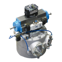
START UP PROCEDURE – USE SEQUENCE
EINSCHALTVERFAHREN - BENUTZUNGSSEQUENZ
PROCÉDURE DE MISE EN MARCHE - SEQUENCE D’UTILISATION
PROCEDURA DI AVVIAMENTO - SEQUENZA DI UTILIZZO
DESCRIZIONE SEQUENZA DI
LAVORO
Dopo aver eseguito scrupolosa-
mente la procedura di avviamen-
to precedentemente descritta si
può iniziare ad utilizzare il devia-
tore VAR.
USCITE
• Come descritto nel paragrafo
Collegamenti Elettrici, le posi-
zioni possibili del tamburo in-
terno sono due:
1) posizione per uscita “I-X” .
(vedi fig. 7 – schema generale
di collegamento)
2) posizione per uscita “I-O”.
(vedi fig. 7 – schema generale
di collegamento)
TENUTE GONFIABILI
• Ogni bocca, sia di entrata che
le due di uscita, sono provvi-
ste di tenute gonfiabili per evi-
tare perdite all’interno del cor-
po.
• Le tenute gonfiabili sono co-
mandate da un solenoide che
ne permette il gonfiaggio o lo
sgonfiaggio (vedi Schema Col-
legamenti Pneumatici ed Elettri-
ci)
POSIZIONAMENTO ROTORE
INTERNO
• Le posizioni di uscita si otten-
gono per mezzo della rotazio-
ne del tamburo interno aziona-
to dall’attautore pneumatico.
• L’attuatore è comandato da una
elettrovalvola a doppio effetto
con due solenoidi.
1) Solenoide per posizione di
uscita “I-X” e rotazione tam-
buro in senso orario (vedi
Schema Collegamenti Pneu-
matici ed Elettrici)
2) Solenoide per posizione di
uscita “I-O” e rotazione tam-
buro in senso anti-orario (vedi
Schema Collegamenti Pneu-
matici ed Elettrici)
SEGNALAZIONE POSIZIONA-
MENTO ROTORE INTERNO
• La posizione del tamburo è se-
gnalata da due micro interrut-
tori posti nella BOX MICRO, di-
rettamente fissata sopra all’at-
tuatore pneumatico.
• Esistono due micro interruttori
azionati da due camme:
1)Micro camma superiore per
segnalazione posizione “I-X”
2)Micro camma inferiore per se-
gnalazione posizione “I-O”
26
DESCRIPTION SÉQUENCE DE
TRAVAIL
Après avoir exécuté scrupuleu-
sement la procédure de mise en
marche décrite précédemment,
on peut commencer à utiliser la
vanne déviatrice VAR.
SORTIES
• Comme décrit dans le paragra-
phe Raccordements Electri-
ques, les positions du tambour
sont deux :
1) position pour sortie “I-X” . (voir
fig. 7 – schéma général de rac-
cordement)
2) position pour sortie “I-O” . (voir
fig. 7 – schéma général de rac-
cordement)
JOINTS GONFLABLES
• Chaque bouche, aussi bien
d’entrée que les deux de sor-
tie, sont dotées de joints gon-
flables pour éviter le fuites à
l’intérieur du corps.
• Les joints gonflables sont com-
mandés par un solénoïde qui
permet le gonflage ou le dégon-
flage (voir Schéma Raccorde-
ments Pneumatiques et Electri-
ques)
POSITIONNEMENT DU ROTOR
INTERNE
• Les positions de sortie s’ob-
tiennent grâce à la rotation du
tambour interne, commandée
par l’actionneur pneumatique.
• L’actionneur est commandé par
une électrovanne à double ef-
fet avec deux solénoïdes.
1) Solénoïde pour position de
sortie “I-X” et rotation tambour
dans le sens horaire (voir Sché-
ma Raccordements Pneumati-
ques et Electriques)
2) Solénoïde pour position de
sortie “I-O” et rotation tambour
dans le sens antihoraire (voir
Schéma Raccordements Pneu-
matiques et Electriques)
SIGNALISATION POSITIONNE-
MENT ROTOR INTERNE
• La position du tambour est si-
gnalée par deux micro-con-
tacts placés dans le BOX MI-
CRO, fixé directement sur l’ac-
tionneur pneumatique.
• Il y a deux micro-contacts ac-
tionnés par deux cames :
1) Micro-contact came supérieu-
re de signalisation position “I-
X”
2) Micro-contact came inférieu-
re de signalisation position “I-
O”
BESCHREIBUNG DER ARBEITS-
SEQUENZ
Nachdem man das vorstehend
beschriebene Einschaltverfah-
ren sorgfältig ausgeführt hat,
kann man mit der Benutzung der
Rohrweiche VAR beginnen.
AUSLÄUFE
• W ie im Abschnitt Elektrische
Anschlüsse beschrieben, kann
die Trommel zwei mögliche Po-
sitionen einnehmen:
1) Position für Auslauf „I-X” (sie-
he Abb. 7 – Allgemeiner An-
schlussplan)
2) Position für Auslauf „I-O” (sie-
he Abb. 7 – Allgemeiner An-
schlussplan)
AUFBLASBARE DICHTUNGEN
• Jede Öffnung, sowohl der Ein-
lauf als auch die beiden Aus-
läufe, haben aufblasbare Dich-
tungen, um zu vermeiden, dass
es innerhalb des Gehäuses zu
Produktverlusten kommt.
• Die aufblasbaren Dichtungen
werden durch eine Solenoids-
pule gesteuert, die das Einlei-
ten und das Ablassen der
Druckluft gestattet (siehe
Schaltplan der pneumatischen
und elektrischen Anschlüsse).
POSITIONIERUNG DES INNEN-
ROTORS
• Die Auslaufposition erhält man
durch die Rotation der Innen-
trommel, die durch den pneu-
matischen Antrieb getätigt wird.
• Der Antrieb wird durch ein dop-
peltwirkendes Magnetventil mit
zwei Solenoidspulen gesteuert.
1) Solenoidspule für die Auslauf-
position “I-X” und die Trommel-
rotation im Uhrzeigersinn (sie-
he Schaltplan der pneumati-
schen und elektrischen An-
schlüsse)
2) Solenoidspule für die Auslauf-
position “I-O” und die Trommel-
rotation entgegen dem Uhrzei-
gersinn (siehe Schaltplan der
pneumatischen und elektri-
schen Anschlüsse)
MELDUNG DER POSITIONIE-
RUNG DES INNENROTORS
• Die Trommelposition wird durch
zwei Mikroschalter gemeldet,
die sich in der MIKROSCHAL-
TERBOX befinden, die direkt
über dem pneumatischen An-
trieb befestigt ist.
• Es gibt zwei Mikroschalter, die
durch zwei Nocken betätigt
werden:
1) Mikroschalter des oberer No-
ckens für Meldung der Position
„I-X”
2) Mikroschalter des unterer No-
ckens für Meldung der Position
„I-O”
WORK SEQUENCE
After having carried out the
switching on procedure strictly
as described earlier, it is
possible to start using the VAR
diverter valve.
OUTPUTS
• As described in the Electrical
Connections paragraph, there
are two possible positions of
the inner drum:
1) position for “I-X” output. (see
Fig. 7 – General connection Di-
agram)
2) position for “I-O” output. (see
Fig. 7 – General connection Di-
agram)
INFLATABLE SEALS
• Each spout, i.e. the inlet spout
and two outlet spouts, are pro-
vided with inflatable seals to
avoid leakage inside the body.
• The inflatable seals are con-
trolled by a solenoid which al-
lows inflation or deflation (see
Pneumatic and Electrical Con-
nections Diagram)
POSITIONING THE INTERNAL
ROTOR
• The output positions are ob-
tained by rotation of the inter-
nal drum operated by the pneu-
matic actuator.
• The actuator is operated by a
double-action solenoid valve
with two solenoids.
1) Solenoid for “I-X” output posi-
tion and clockwise drum rota-
tion (see Pneumatic and Elec-
trical Connections Diagram)
2) Solenoid for “I-O” output posi-
tion and anticlockwise drum ro-
tation (see Pneumatic and Elec-
trical Connections Diagram)
SIGNALLING INTERNAL ROTOR
POSITIONING
• The position of the drum is sig-
nalled by two micro switches
provided in the MICRO SWITCH
BOX fixed directly on top of the
pneumatic actuator.
• There are two micro switches
operated by two cams:
1) Upper cam limit switch to sig-
nal the “I-X” position
2) Lower cam limit switch to in-
dicate the “I-O” position
 Loading...