Installation- and operating manual Handling device HP140T R09-2011
20/52
Product description
3.3 Technical data
3
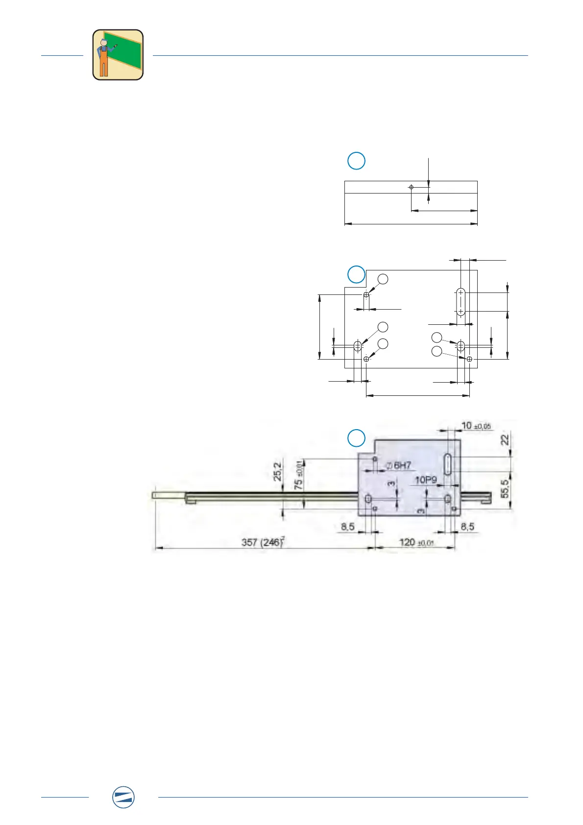
3.3.12 Hole patterns
3.3.12.1Screw hole pattern
Fig. 6: Screw hole pattern
2
stroke horizontal 160 mm
1 Side view base plate
2 Basic housing, HP140T
a Pin holes 6H7
b Long holes for M8 bolts
3 Hole pattern for customer base plate
120 ± 0,01
Ø 6H7
77
7,25
154,5
10 ± 0,05
75 ± 0,01
10P9
8,5
8,5
22
55,5
3
3
2
1
3
a
b
a
b
a
i i i i i i i i i i i i i i i i i
i i i i i i i i i i i i i i i i i
i i i i i i i i i i i i i i i i i
i i i i i i i i i i i i i i i i i
 Loading...