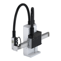
Installation- and operating manual Handling device HP140T R09-2011
4/52
11. Service and spare parts ...................................................................................... 45
11.1. Ordering spare parts ................................................................................... 45
11.2. Spare parts list ............................................................................................ 45
12. Appendix .............................................................................................................. 46
12.1. Index ........................................................................................................... 46
12.2. Personal notes ............................................................................................ 48
Illustration index
General view of the Pick & Place .................................................................................. 13
Example of a type plate ................................................................................................. 14
Axle loads ...................................................................................................................... 15
Installation positions ...................................................................................................... 15
Dimensions .................................................................................................................... 17
Screw hole pattern ........................................................................................................ 18
Adaption gripper ............................................................................................................ 19
Plug-in connections ....................................................................................................... 20
Terminals ....................................................................................................................... 20
Connections for automatic lubrication ........................................................................... 22
Pneumatic valve ............................................................................................................ 23
Tool connector ............................................................................................................... 24
Protective cover on the horizontal axle ......................................................................... 27
Adjustment via long holes ............................................................................................. 29
Firm pinning ...................................................................................................................30
Assembly at a groove .................................................................................................... 31
Gripper front side ........................................................................................................... 32
Gripper left ..................................................................................................................... 32
Gripper right ..................................................................................................................33
Lubricating spring .......................................................................................................... 42
Lubricating axles ........................................................................................................... 43
1
2

 Loading...