52 www.xilinx.com AC701 Evaluation Board
UG952 (v1.3) April 7, 2015
Chapter 1: AC701 Evaluation Board Features
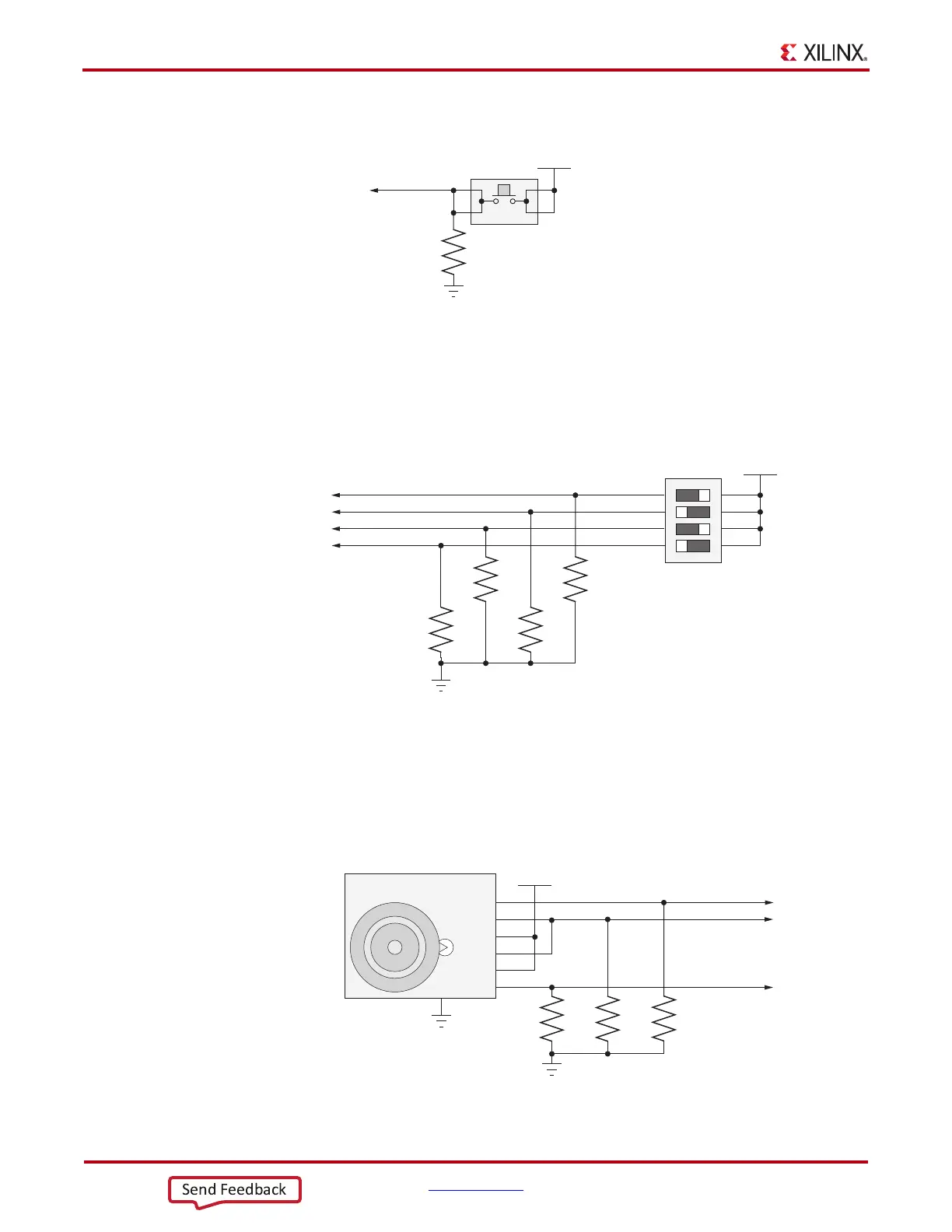
Figure 1-32 shows the user CPU_RESET pushbutton switch circuit.
GPIO DIP Switch
[Figure 1-2, callout 23]
Figure 1-33 shows the GPIO DIP switch circuit.
User Rotary Switch
[Figure 1-2, callout 24]
Figure 1-34 shows the user rotary switch circuit.
X-Ref Target - Figure 1-32
Figure 1-32: CPU_RESET Pushbutton
UG952_c1_140_011813
FPGA_1V5
CPU_RESET
R41
4.7kΩ
0.1 W
5%
GND
4
3 2
1
SW8
X-Ref Target - Figure 1-33
Figure 1-33: GPIO DIP Switch
UG952_c1_30_100412
SDA04H1SBD
SW2
FPGA_1V5
GPIO_DIP_SW0
GPIO_DIP_SW1
GPIO_DIP_SW2
GPIO_DIP_SW3
R53
4.7kΩ
0.1 W
5%
R52
4.7kΩ
0.1 W
5%
R51
4.7kΩ
0.1 W
5%
R50
4.7kΩ
0.1 W
5%
1
2
3
4
8
7
6
5
GND
X-Ref Target - Figure 1-34
Figure 1-34: User Rotary Switch Circuit
UG952_c1_141_011813
VCC3V3
R45
4.7kΩ
0.1 W
5%
R43
4.7kΩ
0.1 W
5%
R44
4.7kΩ
0.1 W
5%
EVQ-WK4001
Edge-Drive Jog Encoder
SW10
B
SW1B
SW2
SW1A
COM
A
GND
6
5
4
3
2
1
GND
ROTARY INCB
ROTARY PUSH
ROTARY INCA
GND
7

 Loading...


