AC701 Evaluation Board www.xilinx.com 53
UG952 (v1.3) April 7, 2015
Feature Descriptions
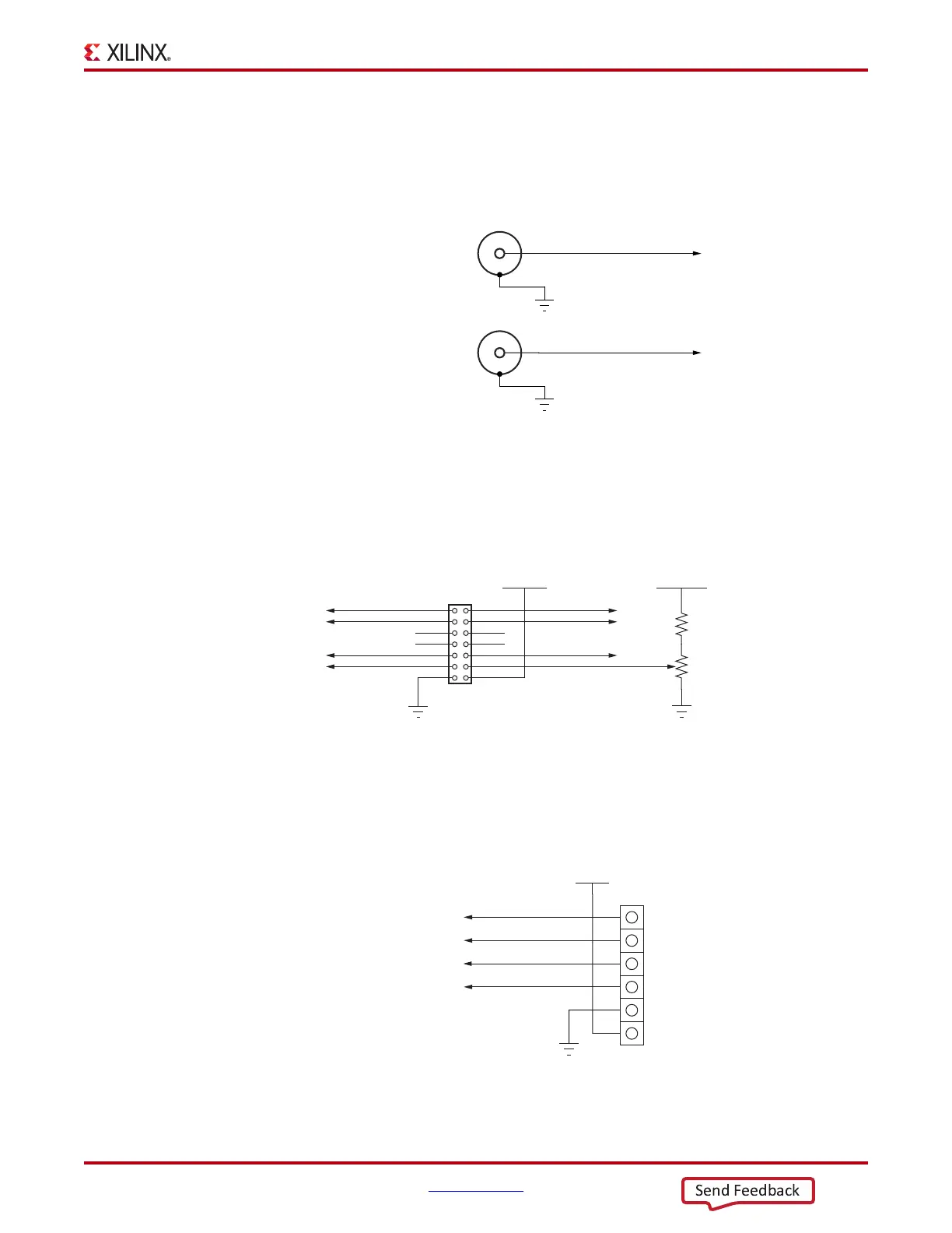
User SMA Connectors
[Figure 1-2, callout 25]
Figure 1-35 shows the user SMA connector circuit.
LCD Connector
Figure 1-36 shows the LCD J23 2x7 male pin header circuit.
PMOD Connector
Figure 1-37 shows the J48 PMOD male pin header.
X-Ref Target - Figure 1-35
Figure 1-35: User SMA Connector
USER_SMA_GPIO_P
J34
USER_SMA_GPIO_N
GND
J33
GND
UG952_c1_142_011813
SMA
Connector
SMA
Connector
X-Ref Target - Figure 1-36
Figure 1-36: LCD Header J23
UG952_c1_31_100412
LCD Contrast
Potentiometer
LCD_RW
LCD_DB4
LCD_DB6
LCD_RS
LCD_E
NC
NC
LCD_DB5
LCD_DB7
9
87
65
43
2
10
1
12
14
11
13
LCD_VEE
J23
GND
VCC5V0
R118
6.81kΩ
R232
2 kΩ
NC
NC
VCC5V0
GND
X-Ref Target - Figure 1-37
Figure 1-37: PMOD Header J48
3
4
5
6
2
1
J48
HDR_1X6
VCC3V3
PMOD_0
PMOD_1
PMOD_2
PMOD_3
GND
UG952_c1_32_100412

 Loading...


