XO FLEX – Installation instructions Installation
23
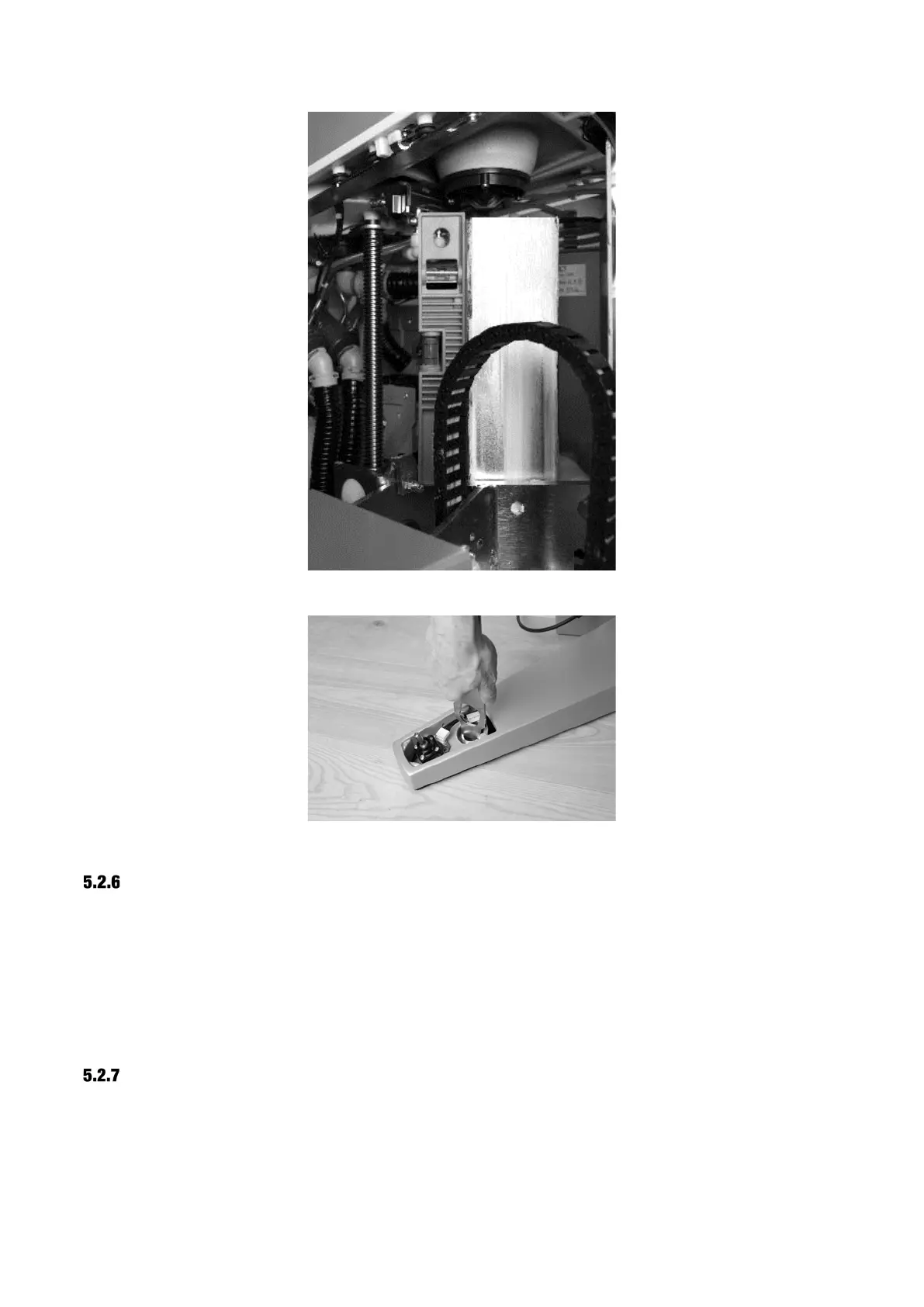
Figure 22 – Adjustment of the chair lift
Figure 23 – Adjustment of the supporting leg
CHECKING CLEARANCE BETWEEN BASE AND FLOOR
During adjustment, it may occur that the unit base or the supporting leg is pressed firmly against
the floor, or alternatively that there is a gap between the rubber sealing and the floor of more than
10 mm.
In either case, the unit base and supporting leg must be re-adjusted using all five adjustment nuts
(see Figure 19).
Note that one turn of an adjustment nut equals a vertical distance of 1.5 mm.
INSTALLATION OF THE UNIT ON A STEEL PLATE
If the unit cannot be mounted directly on the floor, a steel plate for installing the unit is available
(XO-492).
 Loading...

