Alignment
3-5
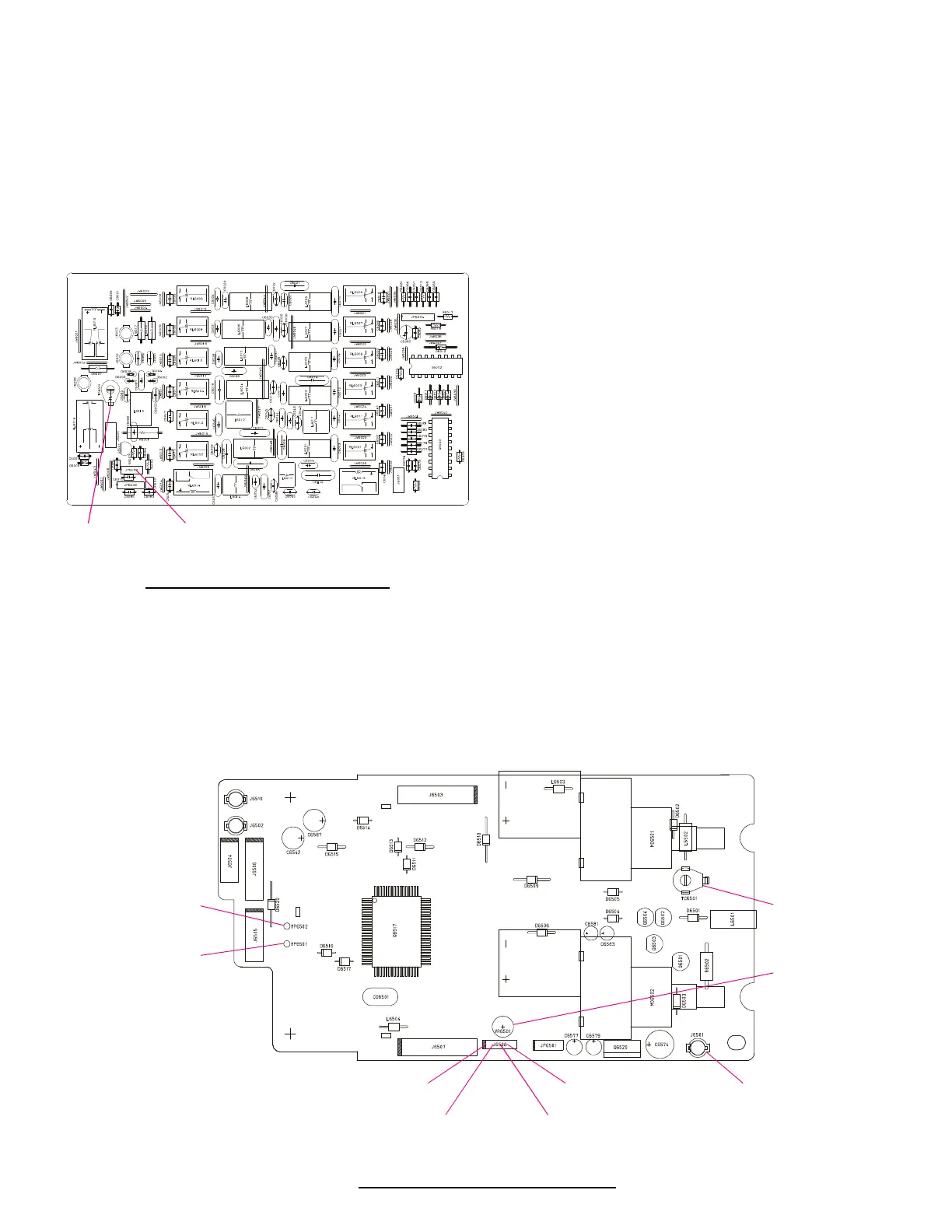
LPF Unit
Refer to the drawing below for LPF Unit component locations
and alignment points.
CM Coupler Balance
r Connect the DC voltmeter to pin 3 of JP6002, connect a 50 W
dummy load to the antenna jack, and select the CW mode.
r Key the transmitter, and adjust TC6001 for minimum indica-
tion on the DC voltmeter.
TUNER-CNTL Unit
Refer to the drawing at the page bottom for TUNER-CNTL
Unit component locations and alignment points.
Tuning Capacitor/Motor
(Mechanical check, setting & adjustment)
r Loosen all set screws in the shaft coupler, and turn the coupler
by hand to confirm it moves freely (the motor and capacitor
should not move).
r If the coupler binds, check the motor mounting position (it is
soldered in place) and the capacitor mounting screw.
r Turn the power switch off, and jumper TP6501 to chassis
ground. Turn the power switch on. The motor should rotate,
and then stop.
r Set the capacitor to its maximum capacitance position (plates
fully meshed) by hand, and tighten all shaft coupler set screw,
using care not to disturb the capacitor or motor positions.
r Turn the power off, and jumper TP6502 to chassis ground
(along with TP6501). Turn the power back on. The motor
should move 180°, and the capacitor should be then at mini-
mum capacitance (fully unmeshed). Remove the grounding
jumpers from TP6501 and TP6502.
Tuner Impedance & Phase Detection
r Connect the 50 W dummy load and wattmeter to J6501 (the
output of the Tuner-Control Unit), and select the CW mode.
r Connect the DC voltmeter between pin-1 (IZIi) and pin-2 (IZIV)
of J6508 (either polarity).
r Press the TUNER and MOX buttons, adjust the RF PWR con-
trol for 50 watts output, and then adjust TC6501, if necessary,
for meter indication within ±0.08 V of 0 V.
r While still transmitting, move the DC voltmeter to pin-3 (fC)
and pin-4 (f L) of J6508 (either polarity), and adjust VR6501,
if necessary, for meter indication within ±0.02 V of 0 V.
LPF Unit Test & Alignment Points
Tuner Unit Test & Alignment Points
TC6001
CM Coupler Balance
JP6002
CM Coupler Balance: Connect DC Voltmeter (minimum)
TC6501
Tuning Impedance &
Phase Detection
J6501
Tuning Impedance &
Phase Detection:
Connect 50 W Dummey with Wattmeter
J6508 Pin-4
Phase Detection:
Connect DC Voltmeter (0 V ± 0.02 V)
J6508 Pin-3
Phase Detection:
Connect DC Voltmeter (0 V ± 0.02 V)
J6508 Pin-1
Phase Detection:
Connect DC Voltmeter (0 V ± 0.08 V)
J6508 Pin-2
Phase Detection:
Connect DC Voltmeter (0 V ± 0.08 V)
VR6501
Phase Detection
TP6502
Tuning Capacitor:
Jumper to GND
TP6501
Tuning Capacitor:
Jumper to GND

 Loading...