27
Use the left and right (lower) buttons to set
the desired display type:
di:00 Multi Function Display. All display
functions can be activated on a
display with di=00 (Log, Wind,
Compass etc.)
di:01 Autopilot Display (with six push
buttons)
di:02 Compass Display with Autopilot
Function (three buttons)
di:03 Trim Flap Display (with six push
buttons)
Display Function:
This selection defines, which function will
be available on a Multi Function Display (i.e.
any display with di=00, independent of the
printing on the display bezel).
The right (lower) button is used to scroll
from one "Function Number" to the next.
The left (lower) button is used to "activate"
or "deactivate" the function. A function has
been activated (can be displayed), if the func-
tion number is steady. A function has been
deactivated (cannot be displayed), if the func-
tion number is blinking:
Primary Functions:
F0 Autopilot Fail Codes (page 50)
11 Gyro signal monitor (for testing only)
20 Log Speed
24 Log Speed 15 sec average (no LED)
23 Trip Distance (resettable)
91 NAV (GPS GND-speed and GND track)
30 Apparent Wind (+/- 180 degrees LED)
31 Apparent Wind (expanded LED)
32 Apparent Wind (0..359 degrees)
34 True Wind angle and speed
28 Rig Load Sensor
61 Heading Hold (with LED pointer)
62 Magnetic Heading (no LED)
75 Depth
Secondary Functions:
33 Mast Angle (for rotating mast)
35 Magnetic Wind (direction and speed)
36 VMG
64 Rate of Turn (deg / sec)
82 Water Temperature
83 Timer
21 Average Trip Speed / Trip Distance
22 Total Log Distance (cannot be reset)
90 NAV (Course, XTE, Dist., Time to WP)
92 D.R. Bearing and Distance from Origin
77 Depth Unit Selection (meters or feet)
81 Voltmeter
Note: for ease of use, activate only the
necessary functions
This function is only avail-
able on an Autopilot Display
(di=01 or di=02).
When that reading is
shown, apply briefly the left or right (lower)
button, to switch to the first Autopilot Parame-
ter "A0". Be careful not to modify A0 inadvert-
ently!
Thereafter the middle (lower) button is
used to scroll to the remaining parameters
"A1" to "A-". The left or right button is used to
alter the respective parameter.
Only A0 and A6 should be modifyed by the
customer during installation. Other parameters
should only be altered after consulting with
the manufacturer.
The customer should receive a diagram
with the recommended parameters for his
vessel.
See page 22/23 for significance of the pa-
rameters.
Autopilot Configuration
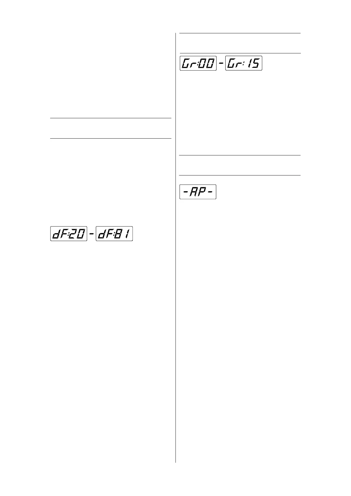
Use the left or right push button to set the
group number of every single display unit:
Gr:00 Group Zero = "Master"; When the illu-
mination level (brightness) is set on a
display with group number zero, all
displays will follow in brightness, inde-
pendent of their own group number.
Gr:01 .. Gr:15 When changing the bright-
ness on a display with group numbers
1 to 15, only those other displays with
the same group number will follow.
Display Group:
 Loading...