Cabling
30
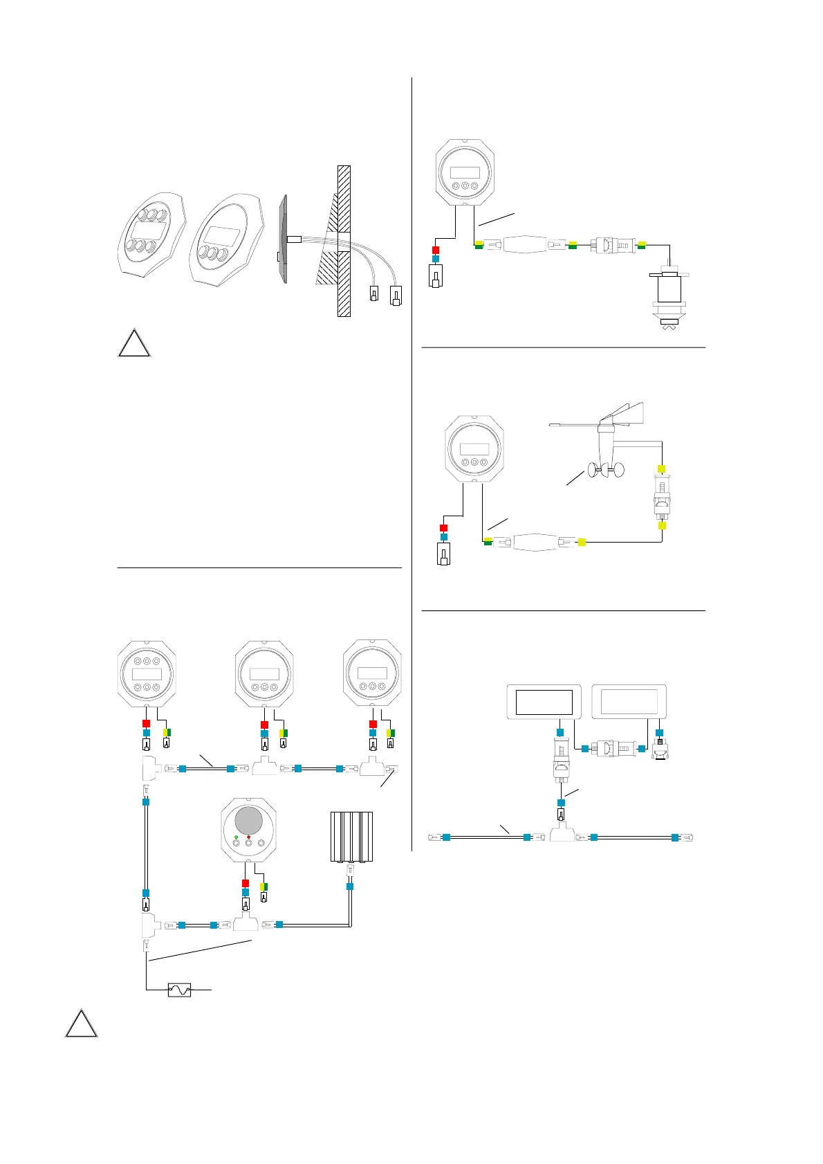
Display Installation
Attention: The cable entrance at
the rear and the plugs must remain
dry.
The displays should be mounted inclined
backwards, so that the LCD will be read
slightly from below. Otherwise the readability
will be degraded at night.
The autopilot display or the compass dis-
play respectively, should be mounted within
reach of the helmsman.
Installation has to be made on a flat sur-
face to avoid bending the display housing.
Bus Cable
BUS
AP Display Log Wind
Bus Power Cable
(11...40 Volts)
white = Plus
brown = GND
Bus terminator plug to be installed at the
most distant point from the bus power cable.
Do not install more than one bus termina-
tor. The second one is installed within the bus
power plug.
ÿþýüû
û
Steering
Wheel
Autopilot
Log Sensor
Log Sensor
Wind Sensor
Wind Sensor
Sensor
Jumbos
Jumbo bus ca-
ble (10m)
Bus
Jumbo Displays
Display
Display
Sensor
B
us terminator
Bus, Power (blue)
NMEA (red)
Electrical Specifications
Cockpit Display:25...50 mA @ 11...40 Volts
(with illumination: 35...90 mA)
Jumbo Display:20...45 mA @ 11...40 Volts
(with illumination: 25...75 mA @ 11..40 Volts)
Steering Wheel: 15...40 mA @ 10,5...40 Volts
Autopilot Computer: 35...70 mA @ 9...40 Volts
Flux Gate Sensor: 45 mA
Sonic Heading Gyro: 5 mA
Wind Sensor: 2 mA
Log Sensor: 2 mA
Echo-Box w/ Sensor: 50 mA
The lower current is for the higher voltage.
Fuse 2A
Bus, Power (blue)
NMEA (red)
 Loading...