CYLINDER HEAD
3. Measure:
• cylinder head warpage
Out of specification → Resurface the
cylinder head.
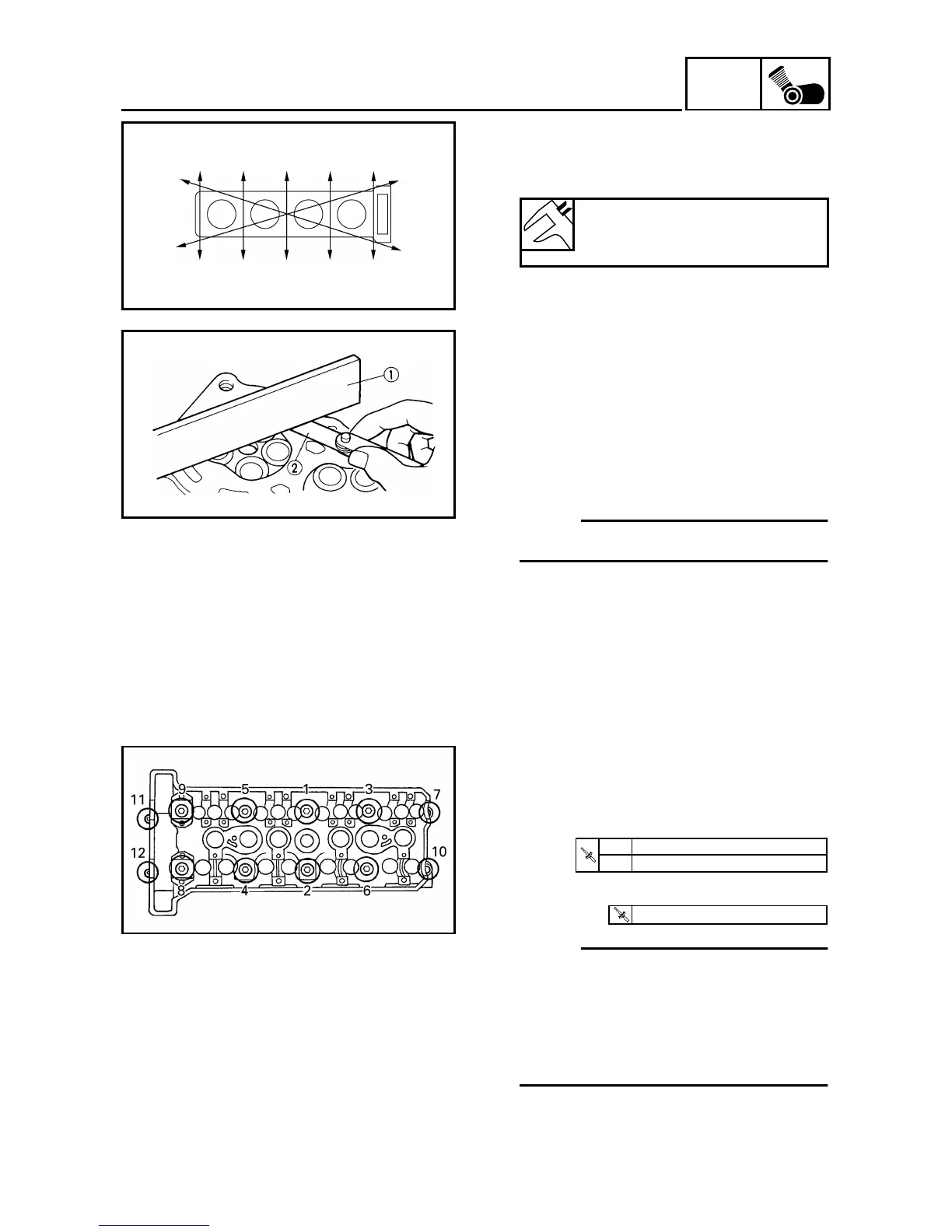
▼ ▼ ▼ ▼ ▼ ▼ ▼ ▼ ▼ ▼ ▼ ▼ ▼ ▼ ▼ ▼ ▼ ▼ ▼ ▼ ▼ ▼ ▼ ▼ ▼ ▼ ▼
a. Place a straightedge 1 and a thick-
ness gauge 2 across the cylinder
head.
b. Measure the warpage.
c. If the limited is exceeded, resurface
the cylinder head as follows.
d. Place a 400 ~ 600 grit wet sandpaper
on the surface plate and resurface the
cylinder head using a figure-eight
sanding pattern.
NOTE:
To ensure an even surface, rotate the
cylinder head several times.
▲ ▲ ▲ ▲ ▲ ▲ ▲ ▲ ▲ ▲ ▲ ▲ ▲ ▲ ▲ ▲ ▲ ▲ ▲ ▲ ▲ ▲ ▲ ▲ ▲ ▲ ▲
Maximum cylinder head
warpage
0.06 mm (0.0024 in)
EB402702
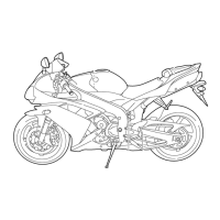
INSTALLING THE CYLINDER HEAD
1. Install:
• cylinder head
• cylinder head nut (1 ~ 10)
• cylinder head bolt (11, 12)
NOTE:
• Lubricate the cylinder head nuts with
engine oil.
• Tighten the cylinder head nuts and
bolts in two stages and in a crisscross
pattern.
• Tighten the nuts and bolts in numeri-
cal order (refer to the numbers in the
illustration).
T
R
.
.
1st. 20 Nm (2.0 m · kg, 14 ft · lb)
2nd. 50 Nm (5.0 m · kg, 36 ft · lb)
T
R
.
.
12 Nm (1.2 m · kg, 8.7 ft · lb)