CONNECTING RODS AND PISTONS
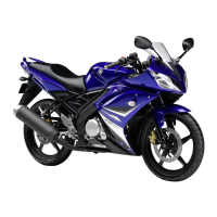
c. Put a piece of Plastigauge
1 on the
crankshaft pin.
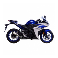
d. Assemble the connecting rod halves.
NOTE:
• Do not move the connecting rod or
crankshaft until the clearance mea-
surement has been completed.
• Lubricate the bolt threads and nut
seats with MOLYKOTE
®
G-n paste.
• Make sure that the “Y” mark c on the
connecting rod faces towards the left
side of the crankshaft.
• Make sure that the characters d on
both the connecting rod and connect-
ing rod cap are aligned.
e. Tighten the connecting rod nuts.
Refer to “INSTALLING THE PISTONS
AND CONNECTING RODS”.
f. Remove the connecting rod and big
end bearings.
Refer to “REMOVING THE CONNECT-
ING RODS AND PISTONS”.
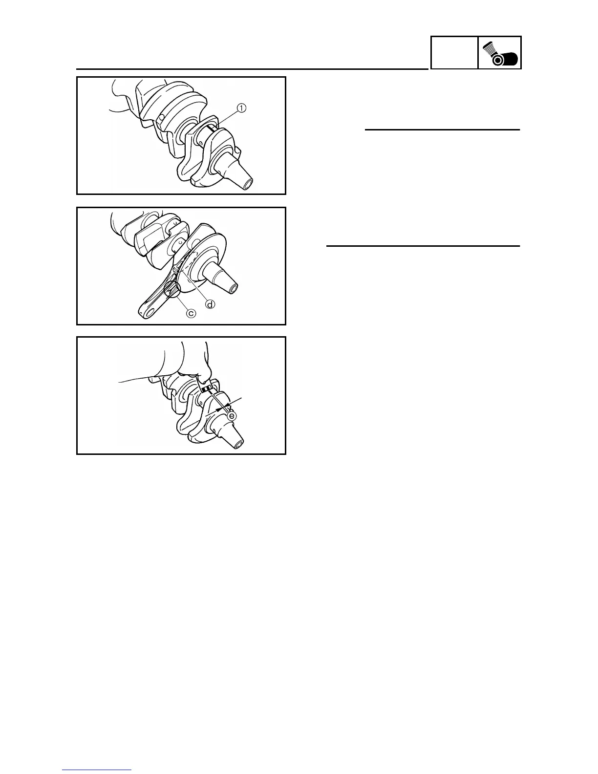
g. Measure the compressed Plasti-
gauge
width e on the crankshaft
pin.
If the crankshaft pin-to-big end bear-
ing clearance is out of specification,
select replacement big end bearings.
▲ ▲ ▲ ▲ ▲ ▲ ▲ ▲ ▲ ▲ ▲ ▲ ▲ ▲ ▲ ▲ ▲ ▲ ▲ ▲ ▲ ▲ ▲ ▲ ▲ ▲ ▲
 Loading...