ELECTRONIC FUEL INJECTION
3. Adjust:
• throttle position sensor angle
▼ ▼ ▼ ▼ ▼ ▼ ▼ ▼ ▼ ▼ ▼ ▼ ▼ ▼ ▼ ▼ ▼ ▼ ▼ ▼ ▼ ▼ ▼ ▼ ▼ ▼ ▼
a. Disconnect the throttle position sen-
sor coupler from the throttle position
sensor.
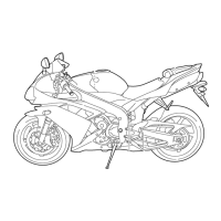
b. Connect the pocket tester (Ω × 1k) to
the throttle position sensor.
c. Measure the throttle position sensor
maximum resistance.
d. Calculate the throttle position sensor
maximum resistance when the throt-
tle is fully closed.
Example:
If the maximum resistance = 5 kΩ, then
the throttle position sensor’s maximum
resistance when the throttle is fully
closed should be:
5 kΩ × (0.13 ~ 0.15) = 650 ~ 750 Ω
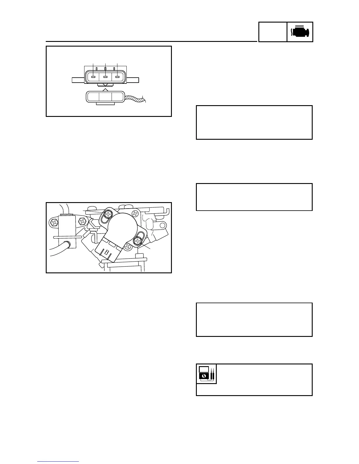
Lift the throttle body assembly slightly
out of the intake manifolds.
Loosen the throttle position sensor
screws 4.
Connect the pocket tester (Ω × 100) to
the throttle position sensor.
e. Adjust the throttle position sensor
angle so that the measured resistance
is within the specified range.
After adjusting the throttle position sen-
sor angle, tighten the throttle position
sensor screws.
▲ ▲ ▲ ▲ ▲ ▲ ▲ ▲ ▲ ▲ ▲ ▲ ▲ ▲ ▲ ▲ ▲ ▲ ▲ ▲ ▲ ▲ ▲ ▲ ▲ ▲ ▲
Positive tester probe →
blue terminal 1
Negative tester probe →
black/blue terminal 2
Throttle position sensor maximum
resistance (throttle is fully closed) =
Maximum resistance × (0.13 ~ 0.15)
Positive tester probe →
yellow terminal 3
Negative tester probe →
black/blue terminal 2
Throttle position sensor resis-
tance
650 ~ 750 Ω
(yellow — black/blue)
B/L
YL
2 3 1
4
4
 Loading...