3 - 10
CHK
ADJ
ADJUSTING THE VALVE CLEARANCE
5. Measure:
• valve clearance
Out of specification → Adjust.
▼ ▼ ▼ ▼ ▼ ▼ ▼ ▼ ▼ ▼ ▼ ▼ ▼ ▼ ▼ ▼ ▼ ▼ ▼ ▼ ▼ ▼ ▼ ▼ ▼ ▼ ▼
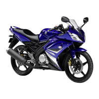
a. Turn the crankshaft clockwise.
b. When piston #1 is at TDC on the com-
pression stroke, align the TDC
mark a on the pickup coil rotor with
the crankcase mating surface b.
NOTE:
TDC on the compression stroke can be
found when the camshaft lobes are
turned away from each other.
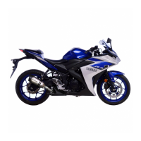
c. Measure the valve clearance with a
thickness gauge 1.
NOTE:
• If the valve clearance is incorrect,
record the measured reading.
• Measure the valve clearance in the fol-
lowing sequence.
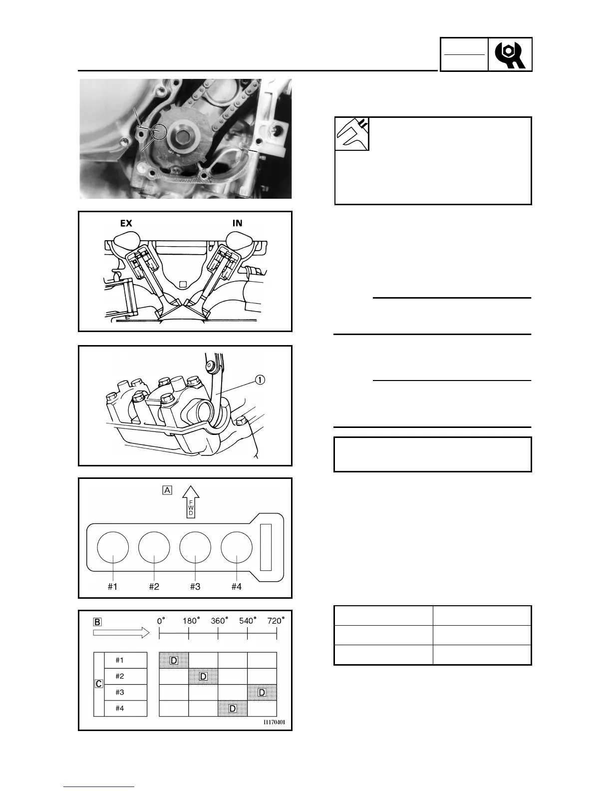
Å Front
d. To measure the valve clearances of
the other cylinders, starting with cyl-
inder #1 at TDC, turn the crankshaft
counterclockwise as specified in the
following table.
ı Degrees that the crankshaft is turned
counterclockwise
Ç Cylinder
Î Combustion cycle
▲ ▲ ▲ ▲ ▲ ▲ ▲ ▲ ▲ ▲ ▲ ▲ ▲ ▲ ▲ ▲ ▲ ▲ ▲ ▲ ▲ ▲ ▲ ▲ ▲ ▲ ▲
Valve clearance (cold)
Intake valve
0.20 ~ 0.25 mm
(0.0079 ~ 0.0098 in)
Exhaust valve
0.25 ~ 0.30 mm
(0.0098 ~ 0.0119 in)
Valve clearance measuring sequence
Cylinder #1 → #2 → #4 → #3
Cylinder #2 180˚
Cylinder #4 360˚
Cylinder #3 540˚
HH
TT
aa
bb
 Loading...