1.2 Part Names and Functions
1-5
1.2
Part Names and Functions
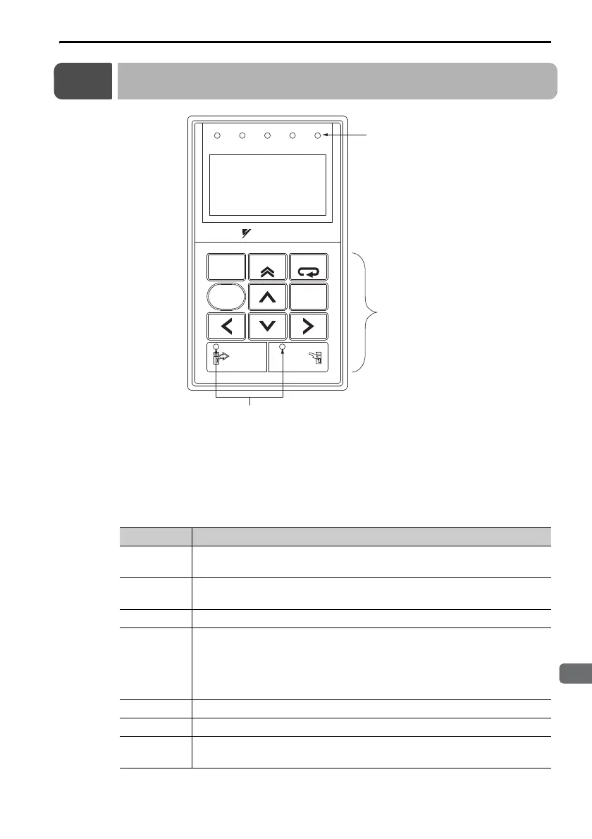
Display and Indicators
The Digital Operator has a display area of five lines with 17 characters
per line. (It uses an LCD.) It also has seven indicators that show status,
such as the servo ON status and positioning completion status. The
indicators are described in the following table.
Indicator Description
SVON
Lit while the servo is ON.
Not lit while the servo is OFF.
COIN
VCMP
Lit when positioning is completed.
Lit during speed coincidence.
TGON Lit while the motor is operating.
REF
Lit when the speed reference input is larger than the rotation
detection level (Pn502).
Position control: Lit while a reference pulse is being input.
Torque control: Lit while the torque reference input exceeds 10%
of the rated torque.
CHARGE Lit while the main circuit power supply is ON.
READ Lit while parameters are being read from the SERVOPACK.
WRITE
Lit while parameters are being written to the SERVOPACK from
the Digital Operator.
Indicators (ve red LED indicators)
LCD
(17 characters × 5 lines)
Operation keys
VCMP
SVON CO IN TGON REF
CHARGE
ALARM
DATA
JOG
SVON
SCROLL
MODE/SET
RESET
SERVO
READ WRITE
SERVO
DIGITAL OPERATOR JUSP-OP05A-1-E
Indicators (red LED 2)
YASKAWA

 Loading...


