113
Interface Connector
Wiring
Universal Serial Bus (USB) Interface
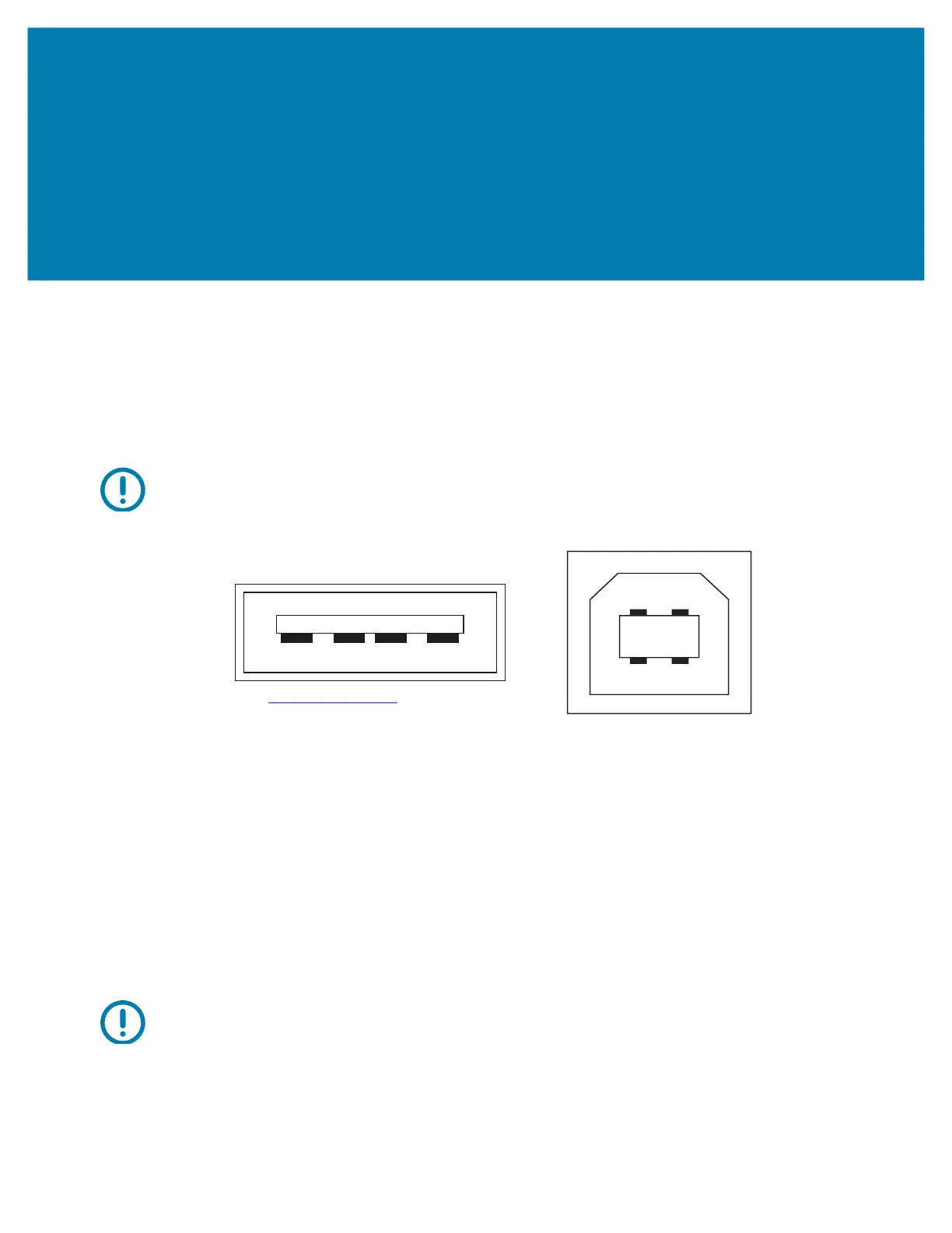
The figure below displays the cable wiring required to use the printer’s USB two interfaces.
Important • When using third party cables, the printer requires USB cables or the cable packaging that bears the
“Certified USB ™ ” mark to guarantee USB 2.0 compliance.
Wiring - USB Connector “A” Style for “connecting to” the printer or device
Pin 1 — Vbus (+5VDC). (Pin 2 — D- (Data Signal, Negative Side)
Pin 3 — D+ (Data Signal, Positive Side)
Pin 4 — Shell (Shield/Drain Wire) Shell
Wiring - USB Connector “B” Style for “connecting to” the printer or device
Pin 1 — Vbus (Not Connected)
Pin 2 — D- (Data Signal, Negative Side)
Pin 3 — D+ (Data Signal, Positive Side)
Pin 4 — Shell (Shield/Drain Wire) Shell
Important • USB Host +5 VDC power source is shared with serial port phantom power. It is limited to 0.5mA per USB
Specification and with on-board current limiting. The maximum current available through the serial port and USB port
will not exceed a total of 0.75 Amps.
http://www.usb.org
A
B
 Loading...