ACH550-UH User’s Manual 1-315
Technical data
Control connections
Control connection specifications
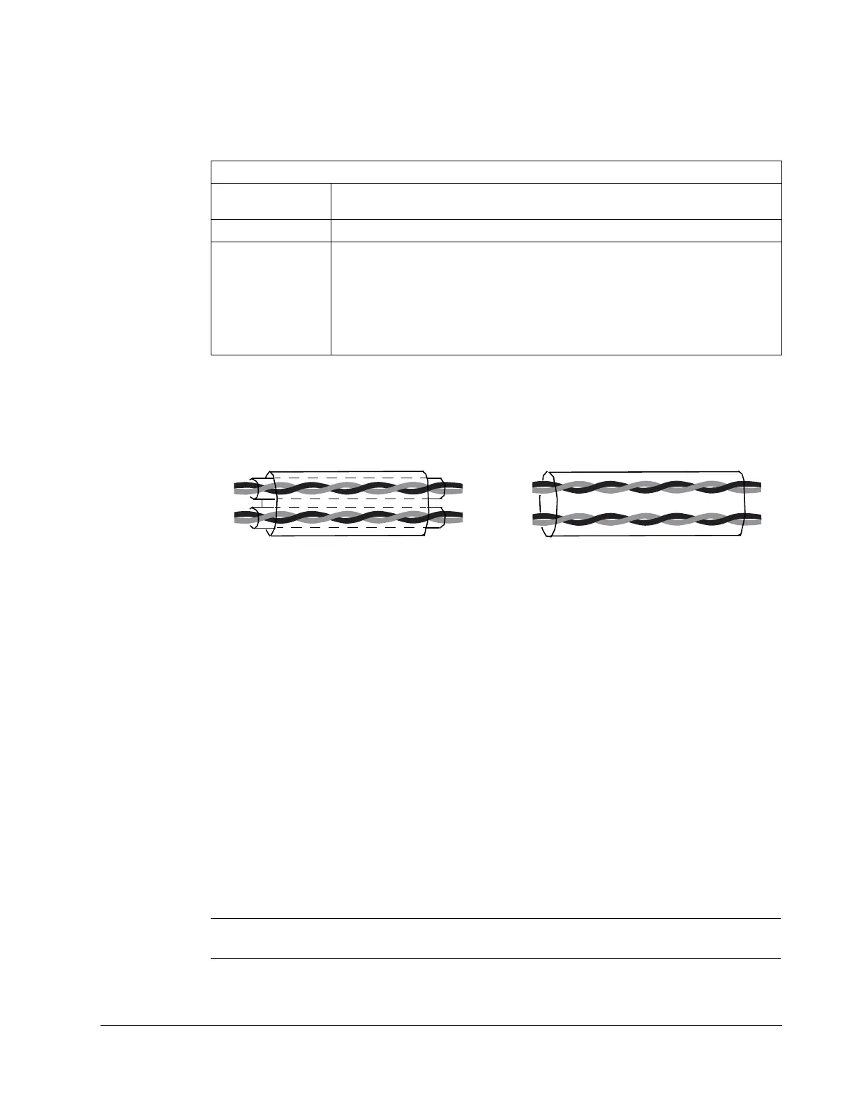
Control cables
General recommendations
Use multi-core cables with a braided copper wire screen, temperature rated at 60 °C
(140 °F) or above:
At the drive end, twist the screen together into a bundle not longer than five times its
width and connected to terminal X1-1 (for digital and analog I/O cables) or to either
X1-28 or X1-32 (for RS485 cables).
Route control cables to minimize radiation to the cable:
• Route as far away as possible from the input power and motor cables
(recommend at least 20 cm [8 in] where practical).
• Where control cables must cross power cables make sure they are at an angle as
near 90° as possible.
• Stay at least 20 cm (8 in) from the sides of the drive where practical.
Use care in mixing signal types on the same cable:
• Do not mix analog and digital input signals on the same cable.
• Run relay-controlled signals as twisted pairs (especially if voltage > 48 V). Relay-
controlled signals using less than 48 V can be run in the same cables as digital
input signals.
Note: Never mix 24 VDC and 115/230 VAC signals in the same cable.
Control Connection Specifications
Analog Inputs and
Outputs
See table heading Drive Control Terminal Description on page 1-317.
Digital Inputs Digital input impedance 1.5 k. Maximum voltage for digital inputs is 30 V.
Relays
(Digital Outputs)
• Max. contact voltage: 30 V DC, 250 V AC
• Max. contact current / power: 6 A, 30 V DC; 1500 VA, 250 V AC
• Max. continuous current: 2 A rms (cos = 1), 1 A rms (cos =0.4)
• Minimum load: 500 mW (12 V, 10 mA)
• Contact material: Silver-nickel (AgN)
• Isolation between relay digital outputs, test voltage: 2.5 kV rms, 1 minute
Double Shielded
Single Shielded
Example: JAMAK by Draka NK Cables
Example: NOMAK by Draka NK Cables
 Loading...


