ACH550-UH User’s Manual 1-59
Application macros
Internal Timer with Constant Speeds / PRV macro
This macro configures for applications such as a timed powered roof ventilator
(PRV) which alternates between two constant speeds (constant speed 1 and 2)
based on a built-in timer.
Momentarily activating digital input 3 (DI3) provides a boost function which operates
the motor. See group 36, Timer Functions, for more information on setting up timers.
Parameters Changed Relative to HVAC Default
Parameter Value
Parameter Value
9902
APPLIC MACRO 9 (INT TIMER CS) 3417 SIGNAL 3 MAX 200.0%
1002
EXT2 COMMANDS 0 (NOT SEL) 3419 OUTPUT 3 UNIT 4 (%)
1103
REF1 SEL 0 (KEYPAD) 3420 OUTPUT 3 MIN -200.0%
1106
REF2 SEL 2 (AI2) 3421 OUTPUT 3 MAX 200.0%
1201
CONST SPEED SEL 15 (TIMER 1) 3601 TIMERS ENABLE 1 (DI1)
1401
RELAY OUTPUT 17 (STARTED) 3622 BOOST SEL 3 (DI3)
1601
RUN ENABLE 2 (DI2) 3626 TIMER 1 SRC 31 (P1+2+3+4+B)
1609
START ENABLE 25 (DI5) 4010 SET POINT SEL 1 (AI1)
3415
SIGNAL 3 PARAM 0105 (TORQUE) 4110 SET POINT SEL 1 (AI1)
3416
SIGNAL 3 MIN -200.0%
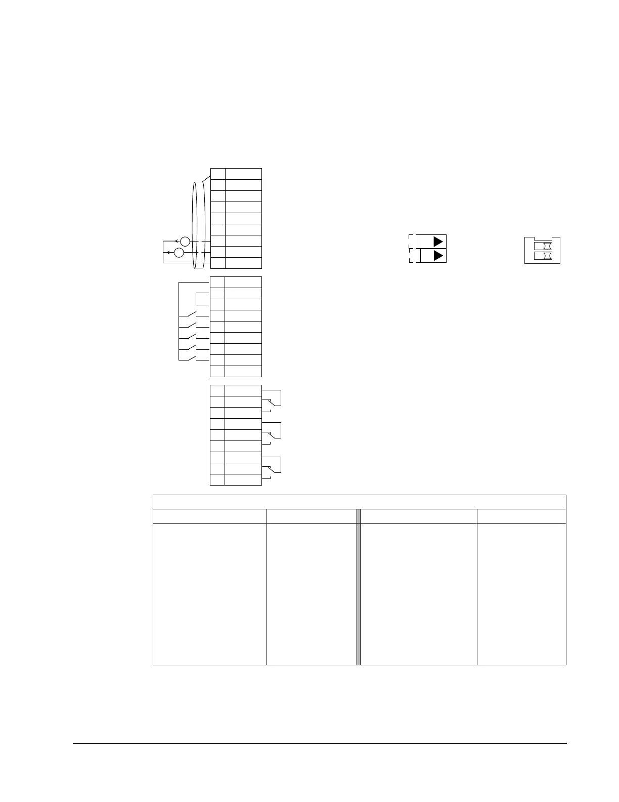
1SCR
2AI1
3AGND
410V
5AI2
6AGND
7AO1
8AO2
9AGND
10 24V
11 GND
12 DCOM
13 DI1
14 DI2
15 DI3
16 DI4
17 DI5
18 DI6
19 RO1C
20 RO1A
21 RO1B
22 RO2C
23 RO2A
24 RO2B
25 RO3C
26 RO3A
27 RO3B
X1
mA
mA
Not configured
Reference voltage 10 VDC
Output frequency: 0(4)…20 mA
Timer enable: Activate to start/stop drive from timer (P 3601)
Run permissive: Deactivate to stop drive (P 1601)
Timer override: Activate to start drive (P 3622)
Safety interlock 1: Deactivate to stop drive (P 1608)
Safety interlock 2: Deactivate to stop drive (P 1609)
Relay output 1 (P 1401)
Default operation: Started =>19 connected to 21
Relay output 2 (P 1402)
Default operation: Running =>22 connected to 24
Relay output 3 (P 1403)
Default operation: Fault (-1) =>25 connected to 27
Output current: 0(4)…20 mA
Not configured
Analog input circuit common
Not configured
Analog output circuit common
Auxiliary voltage output +24 VDC
Auxiliary voltage output common
Digital input common for all
Signal cable shield (screen)
Analog input circuit common
(Fault => 25 connected to 26)
J1
AI1: 0(4)
…20 mA
AI2: 0(4)
…20 mA
ON
J1 Jumper Settings
ON
ON
12
 Loading...


