1-318 ACH550-UH User’s Manual
Technical data
1 Digital input impedance 1.5 k. Maximum voltage for digital inputs is 30 V.
2 Default values depend on the macro used. Values specified are for the HVAC default macro. See
Application macros on page 1-49.
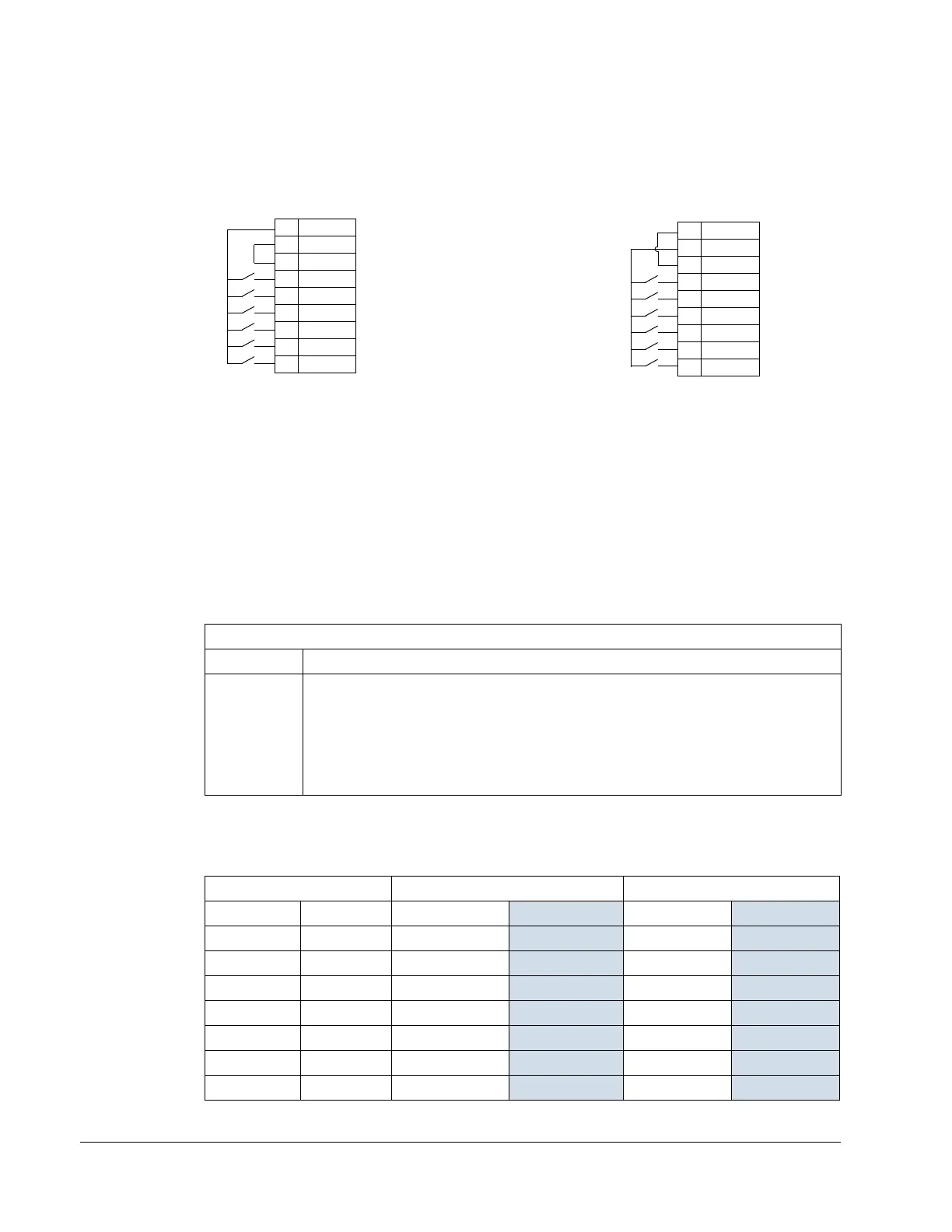
You can wire the digital input terminals in either a PNP or NPN configuration.
Serial communications
Terminals 28
…32 provide RS485 serial communication connections used to control
or monitor the drive from a fieldbus controller. See Embedded fieldbus on
page 1-185 for details.
Efficiency
Approximately 98% at nominal power level.
Cooling
Air flow, 208…240 volt drives
The following table lists heat loss and air flow data for 208…240 volt drives.
Cooling Specifications
Method Internal fan, flow direction from bottom to top.
Requirement
• R1…R6: Free space above and below ACH550 drive: 200 mm (8 in).
• R7/R8: Free space in front of enclosure: 152 mm (6 in).
• R7/R8: Free space above enclosure: None required for cooling.
• R7/R8: Free space at sides of enclosure: None required for cooling – ACH550
enclosures can be mounted side-by-side.
• R7/R8: Also see Additional free space recommendations on page 1-324.
Drive Heat Loss Air Flow
ACH550-xx- Frame Size W
BTU/Hr m
3
/h ft
3
/min
-04A6-2 R1 55 189 44 26
-06A6-2 R1 73
249 44 26
-07A5-2 R1 81
276 44 26
-012A-2 R1 116
404 44 26
-017A-2 R1 161 551 44 26
-024A-2 R2 227
776 88 52
-031A-2 R2 285
373 88 52
NPN connection (sink)PNP connection (source)
10 +24V
11 GND
12 DCOM
13 DI1
14 DI2
15 DI3
16 DI4
17 DI5
18 DI6
10 +24V
11 GND
12 DCOM
13 DI1
14 DI2
15 DI3
16 DI4
17 DI5
18 DI6
X1
X1
 Loading...


