ACH550-UH User’s Manual 1-57
Application macros
Pump Alternation macro
This macro configures for pump alternation applications, usually used in booster
stations. To adjust/maintain pressure in the network, the speed of the one pump
changes according to a signal received from a pressure transducer. When the
variable speed pump reaches a maximum speed limit, auxiliary pumps start as
needed. When using process PID, see General considerations on page 1-49. To use
more than one (the default) Auxiliary pump, see parameter group 81.
Parameters Changed Relative to HVAC Default
Parameter Value Parameter Value
9902
APPLIC MACRO 7 (PUMP ALTERNA) 2203 DECELER TIME 1 10.0 s
1201
CONST SPEED SEL 0 (NOT SEL) 8109 START FREQ 1 58.0 HZ
1401 RELAY OUTPUT 1 31 (PFA) 8110 START FREQ 2 58.0 HZ
1608 START ENABLE 10 (NOT SEL) 8111 START FREQ 3 58.0 HZ
2101 START FUNCTION 8 (RAMP) 8123 PFA ENABLE 1 (ACTIVE)
2202
ACCELER TIME 1 10.0 s
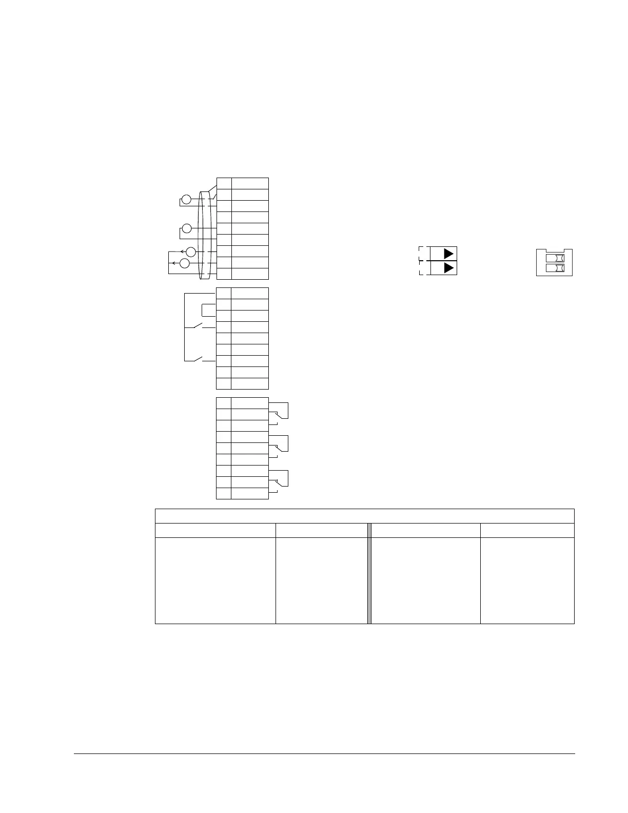
1SCR
2AI1
3AGND
410V
5AI2
6AGND
7AO1
8AO2
9AGND
10 24V
11 GND
12 DCOM
13 DI1
14 DI2
15 DI3
16 DI4
17 DI5
18 DI6
19 RO1C
20 RO1A
21 RO1B
22 RO2C
23 RO2A
24 RO2B
25 RO3C
26 RO3A
27 RO3B
X1
+
mA
mA
External reference 0(2)…10 V or 0(4)…20 mA
Reference voltage 10 VDC
Output frequency: 0(4)…20 mA
Start/Stop: Activate to start drive
Not configured
Not configured
PFA interlock 1: Deactivate to stop drive (P 8120)
Not configured
Relay output 1 (P 1401)
Default operation: PFA (starts lag pump)
Relay output 2 (P 1402)
Default operation: Running =>22 connected to 24
Relay output 3 (P 1403)
Default operation: Fault (-1) =>25 connected to 27
Output current: 0(4)…20 mA
Not configured
Analog input circuit common
PID feedback: 0(2)…10 V or 0(4)…20 mA
Analog output circuit common
Auxiliary voltage output +24 VDC
Auxiliary voltage output common
Digital input common for all
Signal cable shield (screen)
Analog input circuit common
(Fault => 25 connected to 26)
+
J1
AI1: 0(4)
…20 mA
AI2: 0(4)
…20 mA
ON
J1 Jumper Settings
ON
 Loading...


